Super-resolution dual-axis differential confocal measurement method and device for division focal spot detection

A two-axis differential confocal and super-resolution technology, which is applied to measuring devices, optical devices, instruments, etc., can solve the problems of insufficient axial and lateral resolution, suppression of unfavorable light source intensity fluctuations, etc., and improve lateral resolution Effect

Active Publication Date: 2010-08-04
BEIJING INSTITUTE OF TECHNOLOGYGY
View PDF2 Cites 18 Cited by
  • Summary
  • Abstract
  • Description
  • Claims
  • Application Information

AI Technical Summary

Problems solved by technology

[0005] The purpose of the present invention is to overcome the shortcomings of insufficient axial and lateral resolution in the above-mentioned dual-axis confocal microscopy technology, as well as the disadvantages of suppressing factors such as ambient background light and light source intensity fluctuations, etc. The axial response curve of axia

Method used


Image

  • Super-resolution dual-axis differential confocal measurement method and device for division focal spot detection
  • Super-resolution dual-axis differential confocal measurement method and device for division focal spot detection
  • Super-resolution dual-axis differential confocal measurement method and device for division focal spot detection

Examples


Embodiment 1

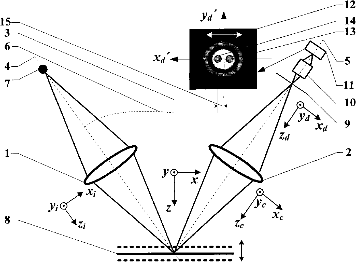
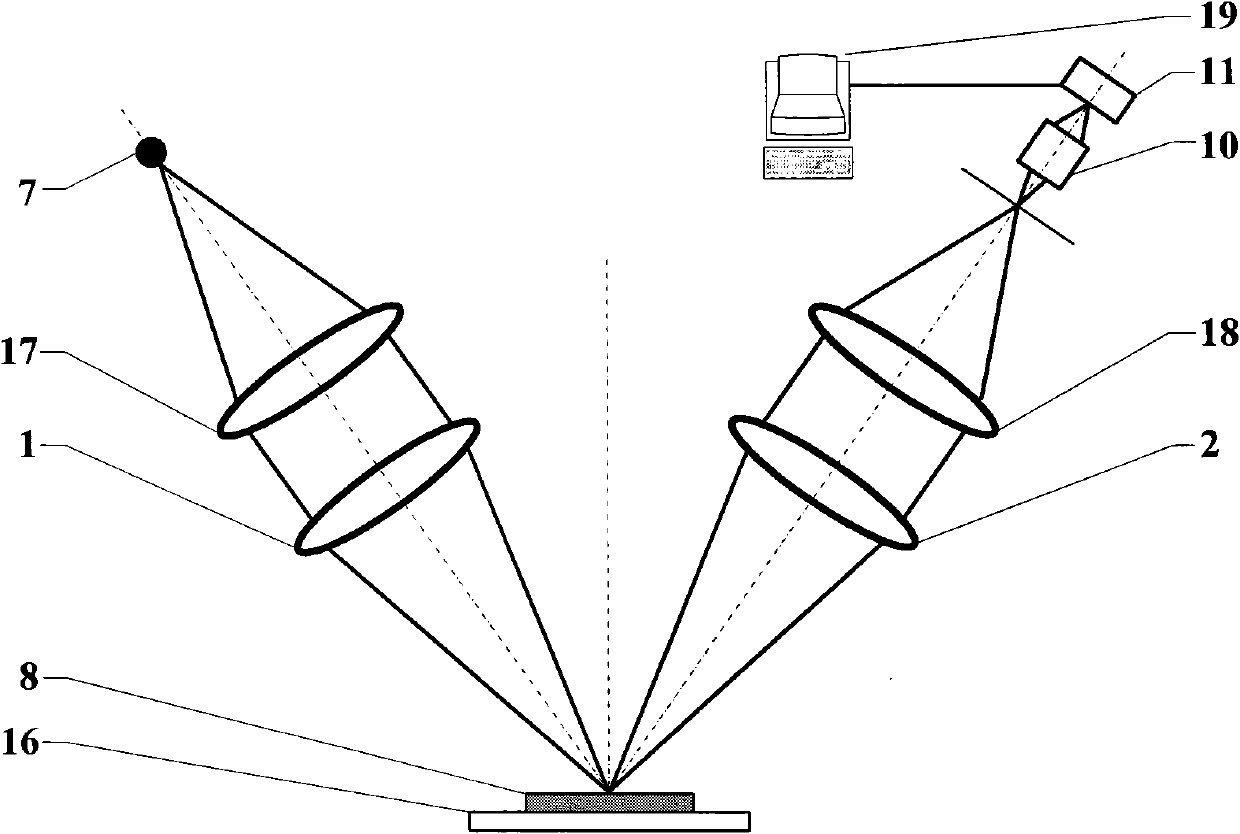
[0053] Such as image 3 As shown, the super-resolution dual-axis differential confocal measurement method for segmented focal spot detection, the measurement steps are:

[0054] First turn on the light source 7 (wavelength λ), and the outgoing light passes through the collimating beam expander 17 and expands the beam to be parallel light. Focusing on the surface of the measured sample 8 placed on the micro-displacement worktable 16, it is reflected into the collection lens 2, and the light beam collected by the collection lens 2 is converged by the measurement lens 18, and the converged light spot is enlarged by the microscope objective lens 10 and imaged on the CCD on detector 23.

[0055] The computer acquires the focal spot image 12 from the CCD detector 23, and when the sample 8 to be measured is located on the focal plane of the system, the computer calculates the center of the focal spot image 12 at this time, and uses the center as the coordinate origin to establish th...

Embodiment 2

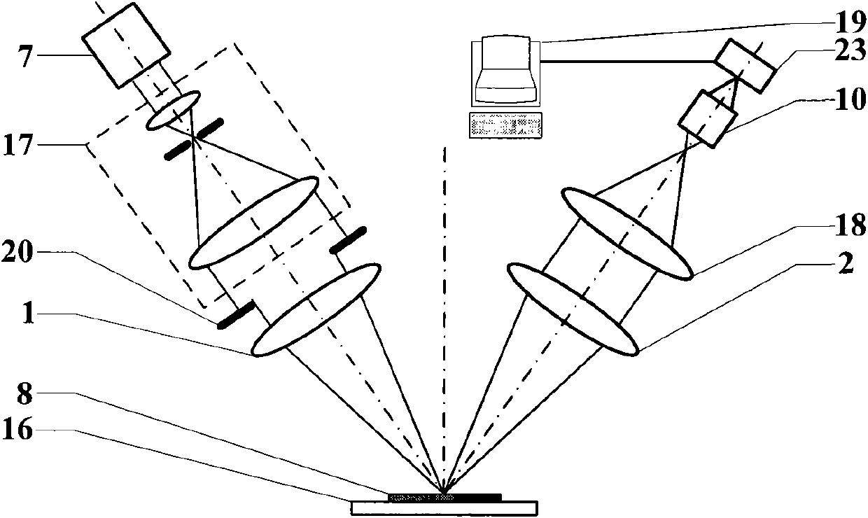
[0076] Such as Figure 6 As shown, the embodiment 1 image 3 A pupil filter 21 at the illumination end is added between the collimator beam expander 17 and the illumination lens 1 to filter and shape the illumination beam, so as to improve the lateral resolution of the system. All the other measuring methods and devices are the same as in Example 1.

Embodiment 3

[0078] Such as Figure 7 As shown, the embodiment 1 image 3 In the method, a pupil filter 22 at the collection end is added between the collection lens 2 and the measurement lens 18 to filter and shape the collection beam, so as to improve the lateral resolution of the system. All the other measuring methods and devices are the same as in Example 1.


PUM


Abstract

The invention relates to super-resolution dual-axis differential confocal measurement method and device for division focal spot detection, which belong to the technical field of optical precision measurement. By utilizing the characteristic that the transversal deflection of a detector makes the axial response curve of the dual-axis confocal microscopy generate displacement, adopting the transversal differential detection method of a division focal spot to receive and process a measuring optical beam in the dual-axis confocal microscopy, and combining a super-resolution pupil filtering technology, the method and the device achieve the purposes of enhancing the system resolution, extending the working distance, enhancing the anti-jamming capability and improving the linear range. The invention can be used for the precision measurement of microelectronics, materials, industry precision detection, biomedical field and the like.

Description

technical field [0001] The invention belongs to the technical field of optical precision measurement and can be used for precision measurement in the fields of microelectronics, materials, industrial precision detection, biomedicine and the like. technical background [0002] Confocal microscopy is widely used in microelectronics, materials, industrial precision testing, biomedicine and other fields due to its unique advantages in optical tomography and high-resolution imaging. However, the existing single-axis confocal microscopes are difficult to balance between resolution, field of view and working distance. Increasing the lens numerical aperture N.A. and reducing the light source wavelength λ can improve the resolving power of the confocal microscope system, but the improvement of the lens numerical aperture N.A. will lead to a shorter working distance and a smaller field of view of the confocal microscope system. At the same time, the light source wavelength λ The redu...

Claims


Application Information

Patent Timeline
IPC IPC(8): G01B11/00G01B9/04
Inventor 赵维谦江琴邱丽荣沙定国
Owner BEIJING INSTITUTE OF TECHNOLOGYGY
Why Eureka
Try Eureka