Phase-shifting full-bridge convertor real-time fault diagnosis method and system

A phase-shifting full-bridge, real-time fault technology, applied to instruments, measuring electrical variables, measuring devices, etc., can solve problems such as long program processing time, difficult application, and inability to accurately locate faults

Inactive Publication Date: 2010-08-04
广州电器科学研究院
View PDF2 Cites 16 Cited by
  • Summary
  • Abstract
  • Description
  • Claims
  • Application Information

AI Technical Summary

Problems solved by technology

The direct measurement method can be divided into two categories: detection of power device variables and detection of other related variables of the circuit. This method is simple and intuitive, and has strong real-time performance, but it cannot accurately locate circuit faults.
Signal processing method, pattern recognition, expert system, neural network and other methods involve complex algorithms, and the program processing time is long, so it is difficult to meet the requirements of power electronic converters with higher and higher operating frequencies. For example, it must be detected within 10μs A short-circuit fault occurs in the power tube of the converter and the fault is eliminated, otherwise the power electronic converter of the bridge topology will have a bad fault state of the bridge arm through
[0003] In general, fault diagnosis methods for power electronic converters that do not rely on mathematical models have the following deficiencies: (1) direct measurement methods cannot accurately locate faults; (2) signal processing methods, pattern recognition and other fault diagnosis involving artificial intelligence The algorithm of the method is complex and difficult to apply in engineering; (3) Failure prediction cannot be realized

Method used


Image

  • Phase-shifting full-bridge convertor real-time fault diagnosis method and system
  • Phase-shifting full-bridge convertor real-time fault diagnosis method and system
  • Phase-shifting full-bridge convertor real-time fault diagnosis method and system

Examples


Embodiment Construction

[0030] The specific implementation manners of the present invention will be further described below in conjunction with the embodiments and accompanying drawings.

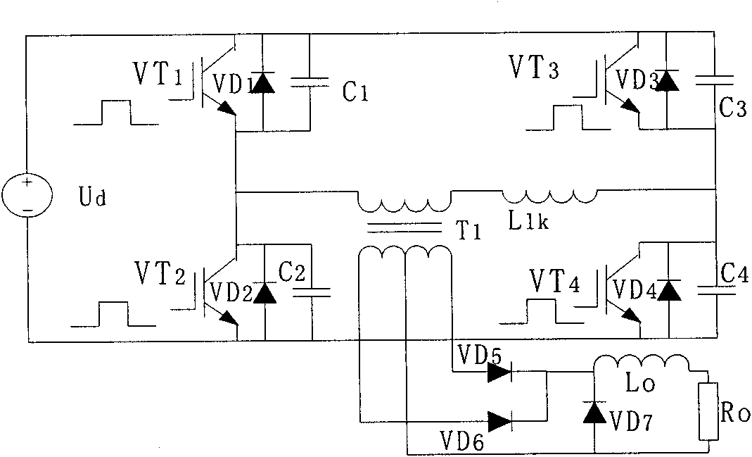
[0031] A real-time fault diagnosis method for a phase-shifted full-bridge converter proposed by the present invention. Current sensors are placed on the two lower bridge arms of the phase-shifted full-bridge converter. The sensor of the lower bridge arm obtains the freewheeling current signal of the power tube anti-parallel diode; in the negative half cycle of the switching cycle, the sensor of the lagging lower bridge arm obtains the freewheeling current signal of the power tube anti-parallel diode; the drive signal of the power tube is combined with the above positive half cycle or The freewheeling current signal obtained by negative half-cycle sampling is used to determine the fault condition of the phase-shifted full-bridge converter according to the logical relationship between the freewheeling current signal o...


PUM


Abstract

The invention discloses a phase-shifting full-bridge convertor real-time fault diagnosis method and a system; two lower bridge arms of a phase-shifting full-bridge convertor are provided with current sensors, in a positive half of a complete switching cycle of the phase-shifting full-bridge convertor, the sensor of the front lower bridge arm obtains a power tube anti-parallel diode freewheel current signal; in the negative half of the switching cycle, the sensor of a rear lower bridge arm obtains a power tube anti-parallel diode freewheel current signal; and the faults of the phase-shifting full-bridge convertor are determined based on the logic relationship between the power tube anti-parallel diode freewheel current signal and a power tube driving signal by integrating the power tube driving signal with the freewheel current signal obtained by the sampling of the positive half or the negative half. The invention can quickly and accurately position the faults and determine the fault types, establish a fault database, and realize fault prediction.

Description

technical field [0001] The invention relates to the field of system fault diagnosis, in particular to a real-time fault diagnosis method and system for a phase-shifted full-bridge converter. Background technique [0002] In the power electronic device, the power device of the main power converter is the weak link most prone to failure. Although the reliability of power device operation has been improved in recent years, it cannot meet the requirements of the power converter. Statistics show that short-circuit and open-circuit are the most common failures of power devices, and phase-shifted full-bridge converters (such as figure 1 ) Power tube faults can be divided into four types: single tube short circuit, double tube short circuit, single tube open circuit and double tube open circuit, and the overvoltage, over current and over temperature of the power tube are the main causes of failure. At present, the technologies adopted for fault diagnosis of power converters can be ...

Claims


Application Information

Patent Timeline
Patent Type & Authority Applications(China)
IPC IPC(8): G01R31/00G01R31/02
Inventor 杜贵平李雄韬
Owner 广州电器科学研究院
Why Eureka
Try Eureka