Top gas confluence method and device of atmospheric and vacuum distillation tower

An atmospheric tower and gas technology, applied in hydrocarbon distillation, petroleum industry, machines/engines, etc., can solve problems such as low extraction rate of vacuum tower, increased stream flow resistance loss, pressure fluctuation of vacuum tower, etc. Achieve the effects of simple process flow, easy implementation and easy transformation

Active Publication Date: 2010-08-11
BC P INC CHINA NAT PETROLEUM CORP +1
View PDF6 Cites 7 Cited by
  • Summary
  • Abstract
  • Description
  • Claims
  • Application Information

AI Technical Summary

Problems solved by technology

However, the operation conditions of most refineries show that the adoption of the existing technology will cause the following problems: the vacuum degree at the top of the vacuum tower often cannot meet the requirements, the pressure fluctuation in the vacuum tower is large, and the operation is unstable, resulting in The pull-out rate is low and the product quality is unqualified
For these jet pumps, the throat section on the nozzle will cause the loss of fluid flow resistance, and the tapered structure adopted behind the nozzle will make the jetted stream directly hit the inner wall of the tapered mixing section after expansion, causing the stream Backflow occurs on the wall surface, forming eddy currents, which increases the resistance loss of stream flow, and is also not conducive to the suction effect on the surrounding micro positive pressure fluid medium

Method used


Image

  • Top gas confluence method and device of atmospheric and vacuum distillation tower
  • Top gas confluence method and device of atmospheric and vacuum distillation tower
  • Top gas confluence method and device of atmospheric and vacuum distillation tower

Examples


Embodiment 1

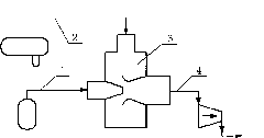
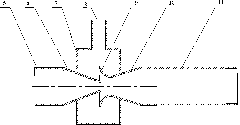
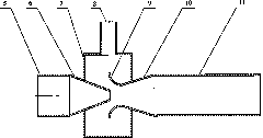
[0027] Example 1. refer to figure 1 and figure 2 . The positive-pressure gas gas (acting as injection medium) separated from the mixed gas tank at the top of the initial distillation tower and the top of the atmospheric pressure tower passes through the primary and constant top gas pipelines 1, enters the injection medium inlet pipe 5 of the confluence 3, and then passes through the confluence After the nozzle 6 is ejected, a flow stream with a higher flow velocity and a constricted vein is produced, and the constricted vein becomes the position with the lowest pressure and the highest suction capacity. The slightly positive pressure gas gas separated from the gas tank at the top of the decompression tower (as the medium to be injected), under the suction of the injection medium, first enters the suction pipe of the medium to be injected in the confluence along the top-reducing gas pipeline 2 8, and then enter the suction chamber 7. The gas to be ejected that enters the c...


PUM


Abstract

The invention discloses a top gas confluence method of an atmospheric and vacuum distillation tower. By the principle that a positive pressure steam generates a vena contracta stream with higher flow speed and lowest pressure after injected at a high speed and entrainment effect on a micro positive pressure gaseous medium around the position of steam vena contracta, the method realizes the confluence of positive-pressure and large-flow gas at the tops of a primary tower and a constant pressure tower of an oil refinery and micro positive pressure and small-flow gas at the top of a vacuum distillation tower. The invention also discloses a top gas confluence device of the atmospheric and vacuum distillation tower, which comprises an injection medium inlet pipe, a spray nozzle, a suction chamber, a medium to be injected inlet pipe, a diffusing section suction opening, a taper gradually diffusing section and a mixing pipe. The invention can realize effective confluence and pressure diffusion of the positive-pressure gas at the tops of the primary tower and the constant pressure tower and the micro positive pressure gas at the top of the vacuum distillation tower, avoid the positive-pressure gas at the tops of the primary tower and the constant pressure tower from returning into gas pipes at the top of the vacuum distillation tower to cause the pressure fluctuation at the top of thevacuum distillation tower, and pressurize and transmit mixed gas to a gas pipeline system of the oil refinery by using a compressor.

Description

technical field [0001] The present invention relates to the technical field of chemical industry and petrochemical industry, specifically, it is a principle of using positive pressure gas jet entrainment to entrain micro positive pressure gas to realize the positive pressure on the top of primary distillation tower and atmospheric pressure tower, large flow rate of gas and gas reduction. A confluence method and device for gas with slight positive pressure and small flow at the top of a pressure tower. Background technique [0002] The initial distillation tower, atmospheric tower and vacuum tower are the "leaders" of the refinery production process - the main devices of the atmospheric and vacuum process. These devices are used to separate crude oil into a large number of primary semi-finished products, such as reformate, hydrogenation material, etc. At the same time as catalytic cracking of secondary deep-processing materials, a large amount of gas or dry gas (mainly compos...

Claims


Application Information

Patent Timeline
Patent Type & Authority Applications(China)
IPC IPC(8): C10G7/00F04F5/16
Inventor 严超宇刘艳升曹睿刘拥军
Owner BC P INC CHINA NAT PETROLEUM CORP
Why Eureka
Try Eureka