Large vacuum solar heat collecting system

A technology of solar heat collection and large vacuum, which is applied in the field of solar heat collection systems, can solve the problems of poor thermal insulation performance, large heat dissipation, and occupying a lot of space, and achieve the effect of ensuring reliability and reducing heat emission

Inactive Publication Date: 2010-08-18
徐旻晖
View PDF0 Cites 6 Cited by
  • Summary
  • Abstract
  • Description
  • Claims
  • Application Information

AI Technical Summary

Problems solved by technology

[0003] At present, the widely used civil solar heat collectors are mainly flat plate type, vacuum glass tube type and the evolution form of vacuum glass tube, heat pipe type. The temperature is relatively low, and the latter is due to the opening of the vacuum glass tube, because the inner tank and the outer shell are forcibly connected to each other here, causing a large amount of heat to be quickly transferred to the outer shell through the inner tank wall and dissipated. It is a common problem of all vacuum glass insulation devices including thermos bottles, so although the insulation capacity of the vacuum insulation layer is strong, the overall heat gain rate is still not high
[0004] In terms of industrial solar thermal power generation, there are relatively mature solar heat collection methods such as tower type, trough type, and dish type system, but they all face the problem of large investment and high cost.
[0005] Most of the existing solar water heaters work independently, and the heat loss in the heat transfer process is relatively large. In addition, the popular compact vacuum glass tube water heaters take up a lot of space due to reasons such as water tanks and installation gaps, resulting in a relatively low heat gain per unit area. Low, great waste of precious solar energy resources in the city

Method used


Image

  • Large vacuum solar heat collecting system
  • Large vacuum solar heat collecting system
  • Large vacuum solar heat collecting system

Examples


Embodiment Construction

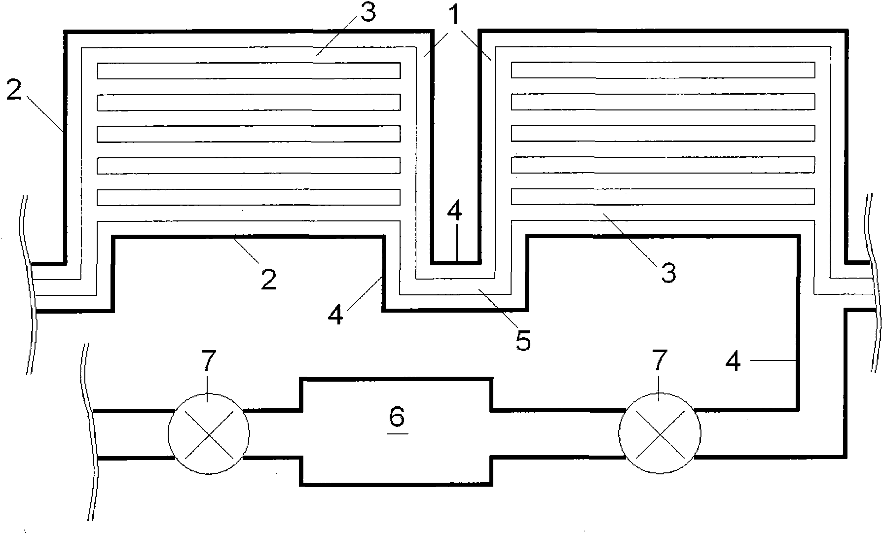
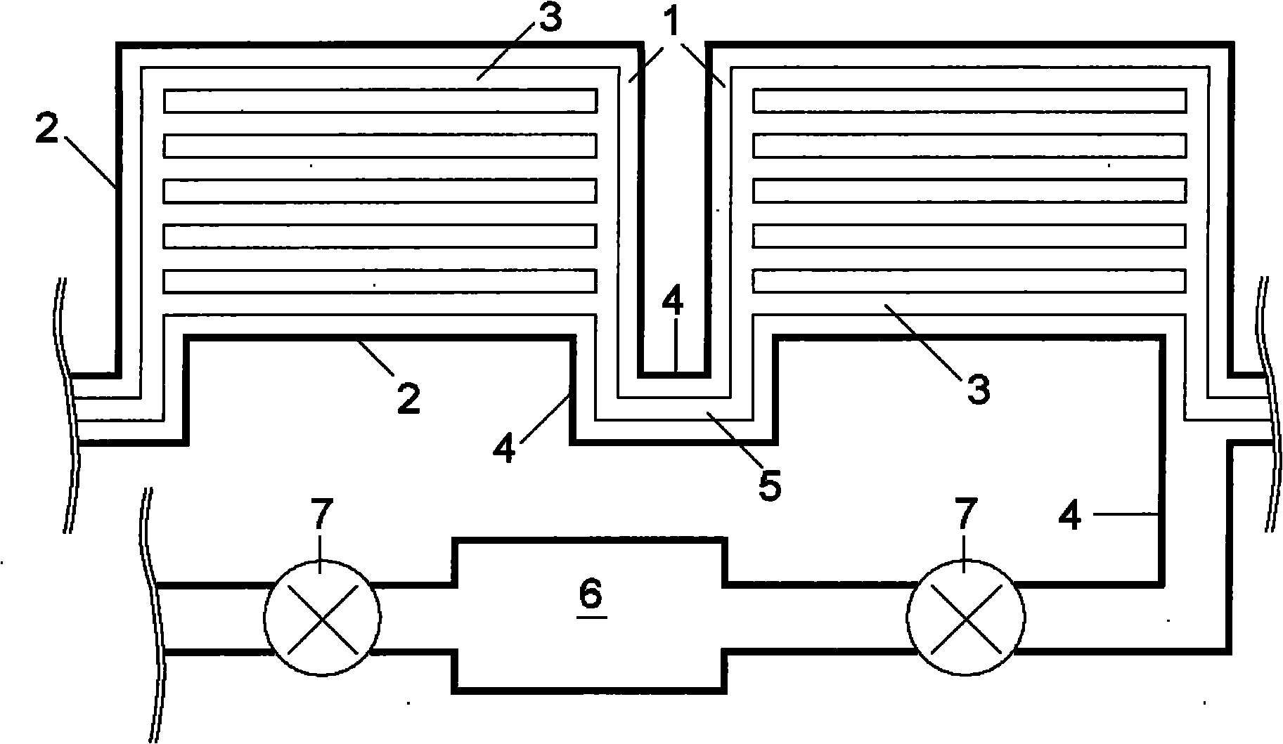
[0016] figure 1 Shown is a schematic diagram of the principle of an embodiment of the present invention. The heat collection system includes a plurality of heat collection units 1. The main structure of the heat collection unit 1 is a shell 2 and a heat absorber 3. The shell 2 is in the shape of a flat box and contains a light-transmitting surface with a high light transmittance. It has a high heat absorption rate and a low heat radiation rate and is placed inside the shell 2. Except for some auxiliary supporting contacts, the rest of the shell 2 should be kept separated as much as possible, and the separated part forms a vacuum heat insulation layer. The shells 2 of the heat collecting units 1 communicate with each other through the vacuum connection pipe 4, so that the vacuum heat insulation layers of the heat collecting units 1 communicate with each other to form a closed large vacuum union.

[0017] The heat collection system also includes a heat transfer pipe 5, which is...


PUM


Abstract

The invention relates to a large vacuum solar heat collecting system comprising a plurality of heat collecting units with vacuum heat insulating layers, each heat collecting unit comprises a shell and a heat absorber, wherein the shells are in a flat box shape and comprise light transmitting faces with higher light transmittance, the heat absorbers have higher heat absorption rates and lower heat radiation rates and are arranged in the shells, the shells of the heat collecting units are communicated with each other through vacuum connecting pipes, and the vacuum heat insulating layers of the heat collecting units are communicated with each other to form a closed large vacuum combination. The heat collecting system also comprises heat energy transmitting pipelines which are arranged in the vacuum connecting pipes and are connected with the heat absorber of each heat collecting unit. In addition, the heat collecting system is also provided with a vacuum supplying maintenance system which comprises a vacuum source, an auxiliary valve, the vacuum connecting pipes and the like and is communicated with the large vacuum combination.

Description

technical field [0001] The invention relates to a solar heat collection system. Background technique [0002] The use of a large amount of mineral energy, in addition to causing human beings to face energy difficulties in the future, has also seriously deteriorated the ecological environment. At the same time, human pursuit of high-quality life has also led to serious shortage and pollution of water resources, and minerals used for sewage treatment Energy has created new environmental pollution. Therefore, vigorously developing and using solar energy has become the consensus of the world today. [0003] At present, the widely used civil solar heat collectors are mainly flat plate type, vacuum glass tube type and the evolution form of vacuum glass tube, heat pipe type. The temperature is relatively low, and the latter is due to the opening of the vacuum glass tube, because the inner tank and the outer shell are forcibly connected to each other here, causing a large amount o...

Claims


Application Information

Patent Timeline
Patent Type & Authority Applications(China)
IPC IPC(8): F24J2/05F24J2/46F24J2/48F24S10/40
CPCY02E10/44
Inventor 徐旻晖
Owner 徐旻晖
Why Eureka
Try Eureka