
High-energy ray laminated type crystal module detector

A high-energy ray and detector technology, applied in radiation measurement, X/γ/cosmic radiation measurement, instruments, etc., can solve the problems of reducing the spatial resolution of detectors, inaccurate positioning, etc. Reduced price, easy to scale effects

Inactive Publication Date: 2010-08-18
TSINGHUA UNIV
View PDF5 Cites 38 Cited by
  • Summary
  • Abstract
  • Description
  • Claims
  • Application Information

AI Technical Summary

Problems solved by technology

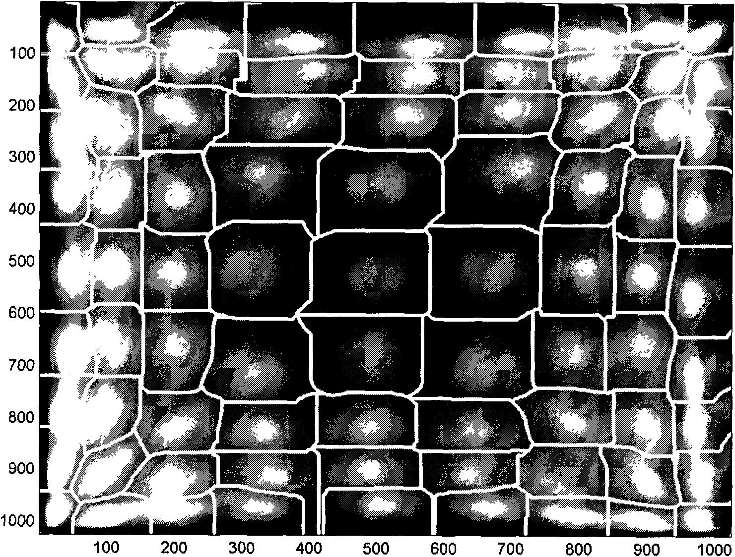
[0006] However, due to the uncertainty of the detection signal, each white clump in the generated pan-field histogram is cross-linked, and its physical meaning is the X, Y signal, in the pan-field histogram, will be judged to act on other long strip crystal units, resulting in inaccurate positioning, thereby reducing the spatial resolution of the detector

Method used


Image

  • High-energy ray laminated type crystal module detector
  • High-energy ray laminated type crystal module detector
  • High-energy ray laminated type crystal module detector

Examples


Embodiment Construction

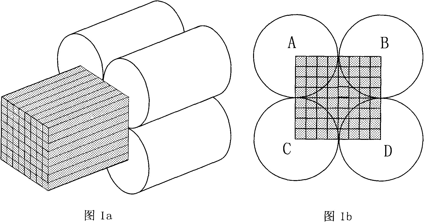
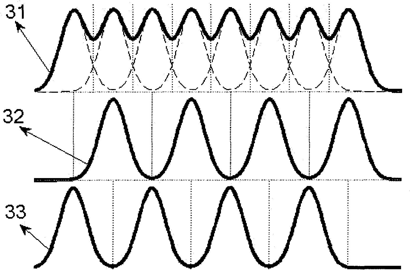
[0031] The invention proposes a novel design method of a high-energy ray laminated crystal module detector. The probe head of the detector is composed of a laminated crystal module coupled with a photomultiplier tube array. The laminated crystal module is formed by alternately arranging elongated crystal units of at least two or more different materials along the width direction, and the alternation includes one direction alternating and two directions alternating. Use optical glue to couple the above-mentioned stacked crystal module with different low-light detector modules. The above-mentioned low-light detector array is connected to the amplification and decoding circuits to obtain the time, space, energy and energy spectrum information of high-energy rays acting on the scintillation crystal. .

[0032]Different luminescence spectra have different decay times. According to the energy spectrum discrimination circuit in the decoding circuit, the material of the elongated cry...


PUM


Abstract

The invention relates to a high-energy ray laminated type crystal module detector which belongs to the technical field of radiation detection imaging. The invention is characterized in that the detector is formed by alternately arraying at least more than two strip type crystal units with different luminescence decay time along the width direction, wherein the alternate arraying method comprises alternating in one direction and alternating in two directions; the laminated type crystal module is coupled with different glimmer detector arrays by utilizing optical cement, and a decoding circuit is added to obtain the high-energy ray detector; high-energy rays are emitted to the crystal module to generate twinkling light; after the twinkling light is converted and amplified through the glimmer detector, an electric pulse signal is obtained and processed to obtain the acting information of energy, time, coordinates, and the like of the high-energy rays; through the screening of the decoding circuit to the pulse signal, a crystal unit material having main action with the high-energy rays is obtained; and the coordinate information is corrected through judging the material. The method can reduce the mistake positioning of the glimmer detector arrays to the position of high-energy ray deposition so as to improve the spatial resolution of the detector.

Description

technical field [0001] The invention relates to a design method of a high-energy ray laminated crystal module detector, belonging to the technical field of radiation detection and imaging. Background technique [0002] One of the commonly used detectors in high-energy ray detection technology is a scintillator detector. It usually uses a scintillation crystal that can effectively block and absorb electromagnetic radiation and produce luminescence with it as a detection material. When high-energy rays are incident into the scintillation crystal, according to the difference in ray energy, effective atomic coefficient and density of the scintillation crystal, different proportions of photoelectric effect, Compton scattering and electron pair effect will occur with the scintillation crystal, and the energy will be deposited in the scintillation crystal. The excited scintillation crystal de-excites a large amount of weak scintillation light, and the de-excitation obeys the law o...

Claims


Application Information

Patent Timeline
Patent Type & Authority Applications(China)
IPC IPC(8): G01T1/202
Inventor 刘亚强王石魏清阳马天予吴朝霞
Owner TSINGHUA UNIV
Learn More