
Cooling device for engine and/or gearbox oil, in particular of a combustion engine

A technology of cooling device and engine oil, which is used in engine cooling, machine/engine, engine lubrication, etc., can solve problems such as large structure space, and achieve the effect of high oil cooling efficiency and simple structure

Active Publication Date: 2010-08-25
MAN NUTZFAHRZEUGE AG
View PDF3 Cites 6 Cited by
  • Summary
  • Abstract
  • Description
  • Claims
  • Application Information

AI Technical Summary

Problems solved by technology

A cooler of this type requires a relatively large installation space

Method used


Image

  • Cooling device for engine and/or gearbox oil, in particular of a combustion engine
  • Cooling device for engine and/or gearbox oil, in particular of a combustion engine
  • Cooling device for engine and/or gearbox oil, in particular of a combustion engine

Examples


Embodiment Construction

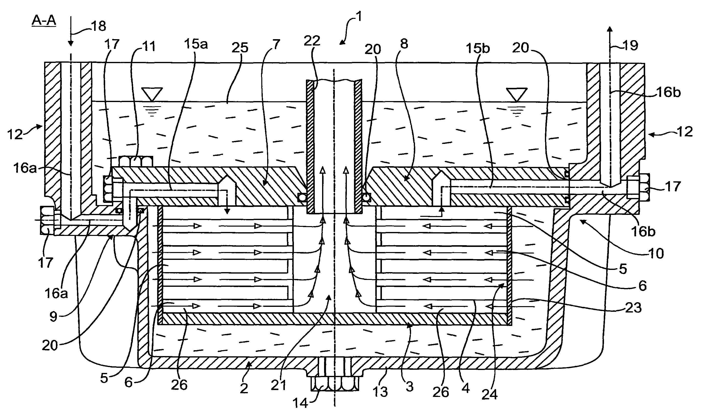
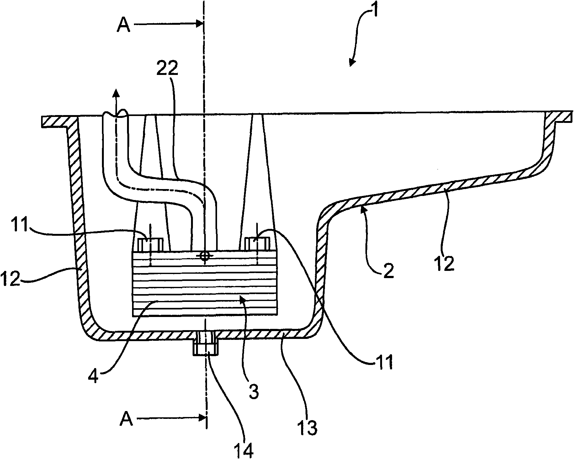
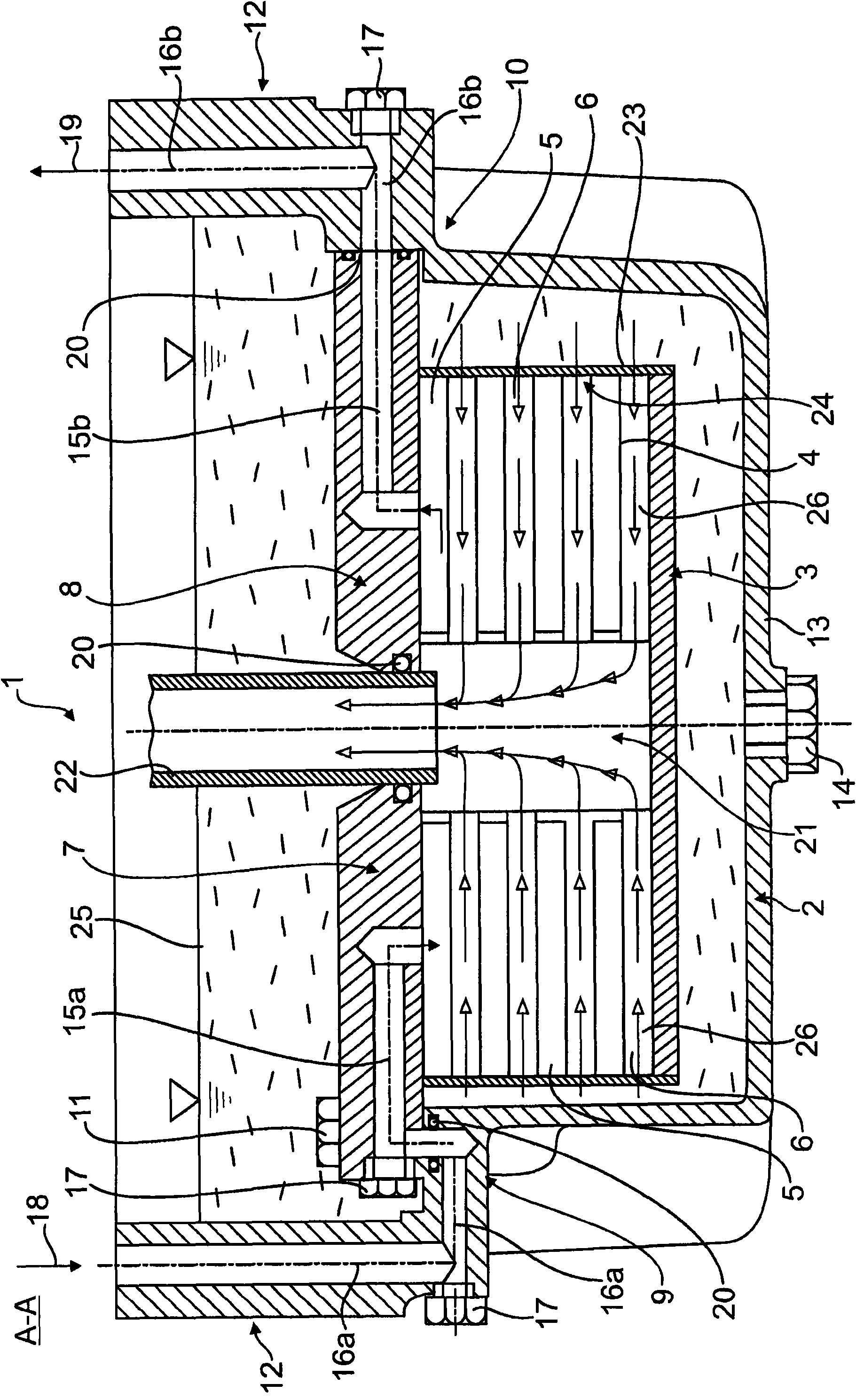
[0026] 1 and 2 schematically show different cross-sectional views through a first embodiment of a cooling device according to the invention. The cooling device 1 comprises a support as an oil cooler and a plate heat exchanger 3 arranged in an oil sump 2 .

[0027] In particular, as can be seen from FIG. 2 , the plate heat exchanger 3 is formed in particular from a stack of several flat plates 4 which on the one hand form the plate intermediate space 5 for supplying the coolant and on the other hand form the supply supply. Oil plate type intermediate chamber 6.

[0028] The plate heat exchanger 3 is thus supported on the bearings 9 , 10 on the side of the oil tank by means of the support elements 7 , 8 on the side of the heat exchanger and fixed, for example by means of screw connections 11 , so that the heat exchanger 3 not only A distance is maintained with respect to the side wall 12 and with respect to the bottom 13 in which usually an oil drain cock 14 is arranged.

[00...


PUM


Abstract

The invention relates to a cooling device for engine oil and / or transmission oil, particularly in an internal combustion engine, with an oil cooler which is arranged in an oil pan and through which a coolant flows. The oil cooler is formed by a plate heat exchanger (3) with coolant-carrying and oil-carrying plate intermediate spaces (5, 6). At least some of the oil-carrying plate intermediate spaces (6) open into the oil pan (2) in such a way the oil flows out of the oil pan directly via the opening (24) into the oil-carrying plate intermediate spaces (6).

Description

technical field [0001] The invention relates to an engine oil and / or transmission oil cooling device according to the preamble of claim 1 , in particular an engine oil and / or transmission oil cooling device for an internal combustion engine. Background technique [0002] It is generally known that such an engine oil and / or transmission oil cooling device is mounted on the engine housing or the transmission housing. In this case, not only the coolant but also the medium to be cooled must be fed to and removed from the cooling device. Such a cooler requires a relatively large installation space. [0003] Furthermore, it is known from DE 10 2004 036 286 A1 to provide an oil cooling device for an engine in which an oil cooler is arranged at a certain distance from the bottom surface within the oil sump. In addition, an oil suction hole is arranged below the cooler here and at a distance from the cooler. With such an arrangement, the efficiency of the oil circulation in the oi...

Claims


Application Information

Patent Timeline
IPC IPC(8): F01M5/00
CPCF01M11/0004F01M2011/0025F01P11/08F01M5/002Y10S165/916
Inventor J·霍尔维克
Owner MAN NUTZFAHRZEUGE AG
Learn More