Stray light correction method of spectrograph

A correction method and stray light technology, applied in the field of spectral radiation measurement, can solve the problems of high manufacturing and maintenance costs of tunable lasers, inability to correct stray light, measurement errors, etc.

Active Publication Date: 2010-08-25
远方谱色科技有限公司
View PDF0 Cites 12 Cited by
  • Summary
  • Abstract
  • Description
  • Claims
  • Application Information

AI Technical Summary

Problems solved by technology

Although this method can greatly reduce stray light and improve measurement accuracy, there are still some problems. First, the manufacturing and maintenance costs of tunable lasers are extremely high, which is difficult for general spectrometer manufacturers and even metrology laboratories to afford; second, this method can only correct all In the measured spectrum, the stray light brought by the optical radiation in the measurement band of the spectrometer cannot be corrected for the stray light produced by the optical radiation outside the measurement band of the spectrometer at each wavelength in the measurement band of the spectrometer. The response wavelength range of the spectrometer is generally wider than the measurement band of the spectrometer. For example, for a spectrometer that measures visible light, the spectral response range of its detector is often in the ultraviolet-visible-infrared range, especially the stray light in the infrared part will bring more big error

Method used


Image

  • Stray light correction method of spectrograph
  • Stray light correction method of spectrograph
  • Stray light correction method of spectrograph

Examples


Embodiment 1

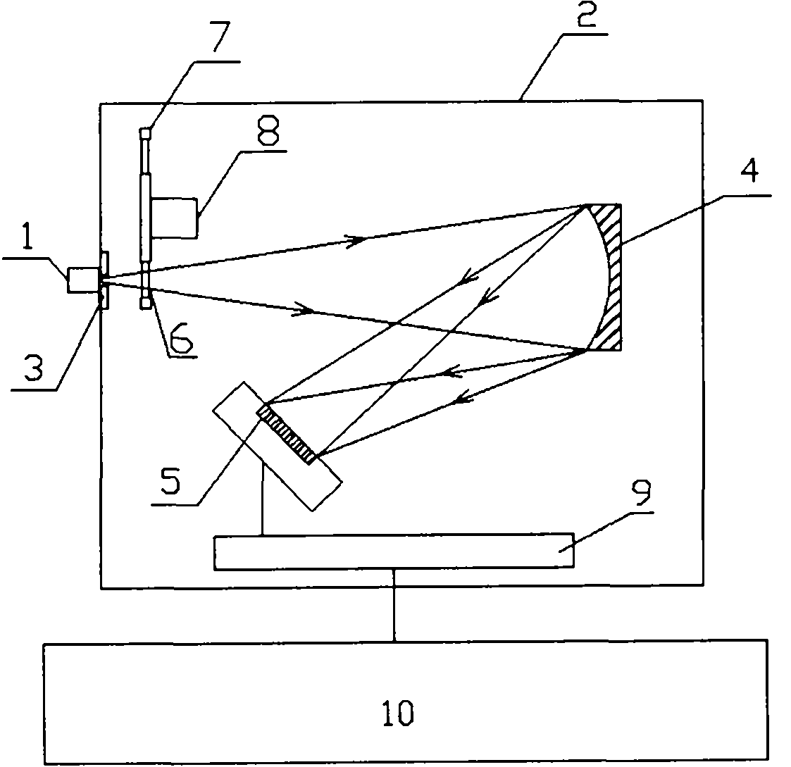
[0065] As shown in Figure 1, it is to realize the structure of a spectrometer of the present invention, including an optical signal acquisition device 1 and an optical platform 2, and the optical platform 2 includes an incident slit 3, a dispersion element 4, an array detector 5 and a microprocessor 9 , a color wheel 7 is arranged between the optical signal acquisition device and the dispersion element, and a group of color filters 6 and through holes 6-4 without any color filters are evenly distributed on the same radius circle of the color wheel; the color wheel 7 and The rotary driving device 8 is connected to cut the color filter 6 or the through hole 6 - 4 on the color wheel 7 into the position of the incident light beam between the incident slit 3 and the dispersion element 4 . The microprocessor 9 is electrically connected with the host computer 10, and the measurement and control software that cooperates with the spectrometer is installed in the host computer 10. The me...

Embodiment 2

[0078] An ultraviolet spectrometer is used, and the measurement band of the spectrometer is 200nm-400nm. A long-pass filter with a cutoff wavelength of 250 nm can be switched between the spectrometer's slit and the grating. When using the spectrometer to measure the UV spectrum of the light source to be tested, the following steps can be used:

[0079] a) Measure the ultraviolet spectral power P without adding a smooth filter f 0 (λ), when the long-pass filter is set, the measured spectral power distribution is P f u (λ);

[0080] b) from the measured P f u (λ) and P f 0 (λ) Calculate stray light distribution factor K f (λ),

[0081] K f ( λ ) = ( P f u ( λ ) - P ...

Embodiment 3

[0088] A spectrometer similar in structure to that in Example 1 was used. The measurement range of the spectrometer is from ultraviolet to visible range of 200nm to 800nm. When using the spectrometer to measure the UV spectrum of the light source to be tested, the following steps can be used:

[0089] a) Use a spectrometer to measure 5 laser beams with a wavelength distribution between 400nm and 800nm ​​respectively, and obtain the spectral power distribution of each laser beam;

[0090] b) Calculate the first stray light distribution factor generated by the optical radiation corresponding to the wavelength of the laser at other wavelengths according to the following formula:

[0091] K l λ ' ( λ ) = P l λ ' ( λ ...


PUM


Abstract

The invention discloses a method and a device for correcting stray light of a spectrograph. A plurality of color filters capable of being cut in are arranged on a light path between a light signal entering slit and a color dispersion element of the spectrograph, the same light source to be measured is respectively measured when each color filter is cut in and when light filters are not cut in, stray light distributing factors are calculated by the measured spectrum, the stray light error of the light source to be measured or other light sources is corrected and measured by using the stray light distributing factors, and the color filters can also be combined with laser to further correct the stray light; or the color filters and the laser are combined to correct the stray light generated by light radiation outside the measuring waveband of the spectrograph, and the stray light in the measuring waveband of the spectrograph is corrected by using the laser; and the corresponding measurement and control software of the spectrograph comprises a stray light correction program capable of conveniently and rapidly realizing the correction of the stray light. The invention can realize the correction of the stray light in the measuring waveband of the spectrograph and the stray light caused by the light radiation outside the measuring waveband and has convenient operation and is easy to realize high-precision spectral measurement.

Description

【Technical field】 [0001] The invention belongs to the field of spectral radiation measurement, and in particular relates to a method for correcting stray light of a spectrometer. 【Background technique】 [0002] Spectrometers are used to measure the spectral power distribution of light radiation, and are widely used in color measurement, element identification, chemical analysis and other fields. Stray light is unavoidable in spectrometers due to imperfect diffraction from gratings, scattering caused by dust or defects on optical components, and various reflections inside the instrument. For a fast spectrometer with an array detector, stray light refers to other spectral components irradiated on the pixel corresponding to a specific wavelength point, which will bring considerable measurement errors. The level of stray light is one of the important technical indicators to measure the performance of the spectrometer. The stray light can be reduced to a reasonable level by car...

Claims


Application Information

Patent Timeline
Patent Type & Authority Applications(China)
IPC IPC(8): G01J3/02G01J3/28
Inventor 潘建根陈双李倩
Owner 远方谱色科技有限公司
Why Eureka
Try Eureka