Ammeter wireless monitoring interface devices and wireless monitoring system

A wireless monitoring and interface device technology, applied in non-electrical signal transmission systems, measurement devices, signal transmission systems, etc., can solve the problems of high construction cost, large mutual interference of signals, waste of electricity meters, etc., and achieves high data transmission rate, Simple installation and configuration, strong anti-interference effect

Inactive Publication Date: 2012-03-21
NANHUA UNIV
View PDF4 Cites 0 Cited by
  • Summary
  • Abstract
  • Description
  • Claims
  • Application Information

AI Technical Summary

Problems solved by technology

The current automatic meter reading technology is mainly divided into two categories: wired and wireless. Due to the complicated installation of wired automatic meter reading technology, high maintenance costs and small coverage, the application of wireless automatic meter reading technology is becoming more and more extensive.
Chinese patent application CN1304030A (patent application number is 00114330.1) and CN1414346A (patent application number is 02110461.1) all disclose the remote meter reading system based on wireless, although these systems can carry out the transcription and management of electric meter data, but they can not realize two-way communication, And the cost is higher
Chinese patent application CN101425219A (patent application number 200710056240.3) discloses a smart remote electricity meter based on a wireless sensor network, which includes a dedicated radio frequency unit, a microcontroller unit, a power management unit, a power information collection unit, an external storage unit, a liquid crystal Display unit and fault detection unit; although it can realize the two-way transmission of information between the remote power supply enterprise and the user's electric meter, it requires the user to install or replace the electric meter described in the patent application, which will cause a lot of waste of electric meters; in addition, the patent also Does not have prepayment and anti-stealing functions, and cannot well meet the current application requirements
[0005] 1. The concentrator is connected to several ammeters through PLC, and the power line is affected by the load, which makes the impedance on the line fluctuate greatly, which affects the reliability of the signal; for areas with dense users, there are more ammeters on the same power line , they are in the same broadcast domain, and the signals interfere with each other a lot. In addition, the transmission rate of the power carrier is low, so the real-time performance of monitoring is poor; when the line is powered off, the monitoring center will lose the monitoring of the state of the meter. Give criminals the opportunity to take advantage of the situation; in addition, the power line is restricted by the region, and the power carrier signal is not convenient for cross-regional transmission;
[0006] 2. When using GPRS, PSTN or radio to realize real-time information transmission, it is necessary to rent a public network, and the cost is relatively high;
[0007] 3. The system needs electric meters with PLC and RF modules, which makes the system construction cost higher, and the user must replace the electric meters.

Method used


Image

  • Ammeter wireless monitoring interface devices and wireless monitoring system
  • Ammeter wireless monitoring interface devices and wireless monitoring system
  • Ammeter wireless monitoring interface devices and wireless monitoring system

Examples


Embodiment 1

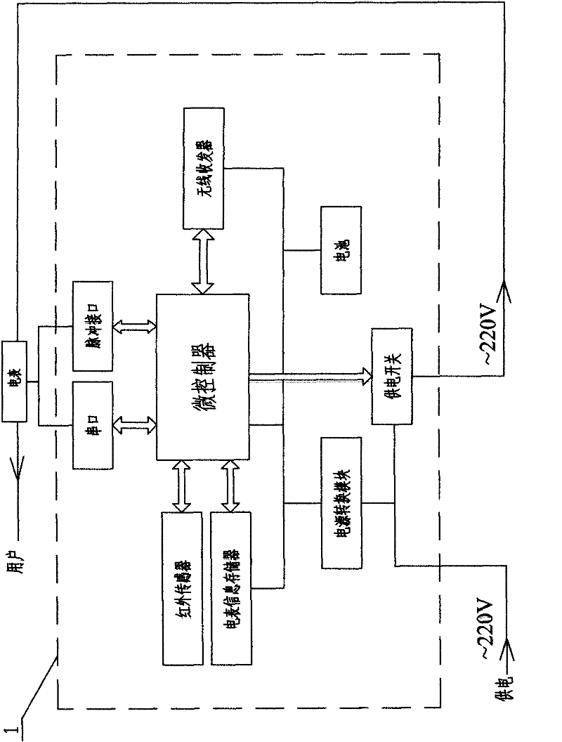
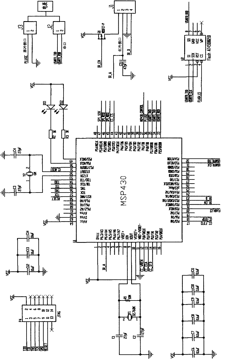
[0035] Such as Figure 1-2 As shown, a wireless monitoring interface device for an electric meter mainly includes a microcontroller, an electric meter information memory, a wireless transceiver, an infrared sensor, a power supply, and a power supply switch; MSP430 has rich interfaces and stable performance. MSP430 adopts TinyOS 1.x operating system. TinyOS 1.x is a dedicated operating system for wireless sensor networks based on components, modules and event-driven. It occupies a small space and runs fast; the meter information memory uses 2MB Serial FlashAT45DB021D storage chip, the chip external circuit is simple, small size, low power consumption, meter information memory FlashAT45DB021D through the SPI serial interface (that is, 1-pin SI terminal, 8-pin SO terminal, 2-pin SCK terminal) and the microcontroller The I / O interface of the USARTO / UART mode of the MSP430 (that is, the 32-pin P3.4 / UTXDO terminal, the 33-pin P3.5 / URXDO terminal, and the 31-pin P3.3 / UCLKO terminal o...

Embodiment 2

[0042] Such as Figure 7 As shown, a wireless monitoring system for electric meters includes a wireless sensor network for electric meters and a wireless community monitoring center 3. The wireless sensor network for electric meters includes more than one wireless monitoring interface device 1 for electric meters, and each wireless monitoring interface device 1 for electric meters is connected to a user electric meter Each meter wireless monitoring interface device 1 constitutes a node of the meter wireless sensor network. On the one hand, the meter wireless monitoring interface device 1 can communicate with the user's meter (read and write meter information), and on the other hand, it is responsible for building the meter wireless sensor network. The electric meter wireless monitoring interface device 1 communicates with the community wireless monitoring center 3 through the electric meter wireless sensor network, that is, the electric meter wireless monitoring interface devic...


PUM


Abstract

The invention relates to an ammeter wireless monitoring system which comprises an ammeter wireless sensor network and a community wireless monitoring center (3). The community wireless monitoring center (3) comprises a central information management control system (31) and a central wireless transmitter (32), and the ammeter wireless sensor network comprises more than one ammeter wireless monitoring interface device (1) and building wireless repeater (2), wherein each ammeter wireless monitoring interface device (1) is connected with a user ammeter and forms a node of the ammeter wireless sensor network, each building wireless repeater (2) forms a convergent node of the ammeter wireless sensor network, and the community wireless monitoring center (3) remotely manages and controls the ammeter by the ammeter wireless sensor network.

Description

technical field [0001] The invention relates to equipment and a system for remote wireless management and control of electric meters, in particular to a wireless monitoring interface device for electric meters and a wireless monitoring system. Background technique [0002] As society's demand for electricity increases day by day, power supply companies increasingly need methods that can effectively monitor and control user electricity meters. The current automatic meter reading technology is mainly divided into two categories: wired and wireless. Due to the complicated installation of wired automatic meter reading technology, high maintenance costs and small coverage, the application of wireless automatic meter reading technology is becoming more and more extensive. Chinese patent application CN1304030A (patent application number is 00114330.1) and CN1414346A (patent application number is 02110461.1) all disclose the remote meter reading system based on wireless, although th...

Claims


Application Information

Patent Timeline
Patent Type & Authority Patents(China)
IPC IPC(8): G08C17/02G08C23/04G01R11/24
Inventor 谭敏生田海涛黄欣阳蒋卫国赵治国
Owner NANHUA UNIV
Why Eureka
Try Eureka