Bushing-type high temperature heat storage device applied to solar heat utilization

A technology for solar thermal and thermal storage devices, applied in solar thermal devices, solar thermal power generation, heating devices, etc., to achieve the effects of small phase segregation, high latent heat of phase transition, and long service life

Inactive Publication Date: 2010-09-01
HUBEI KAIJIA ELECTRICAL TECH GROUP
View PDF2 Cites 9 Cited by
  • Summary
  • Abstract
  • Description
  • Claims
  • Application Information

AI Technical Summary

Problems solved by technology

Therefore, research on high-temperature heat storage devices (>400°C) needs to be further developed.

Method used


Image

  • Bushing-type high temperature heat storage device applied to solar heat utilization
  • Bushing-type high temperature heat storage device applied to solar heat utilization
  • Bushing-type high temperature heat storage device applied to solar heat utilization

Examples


Embodiment 1

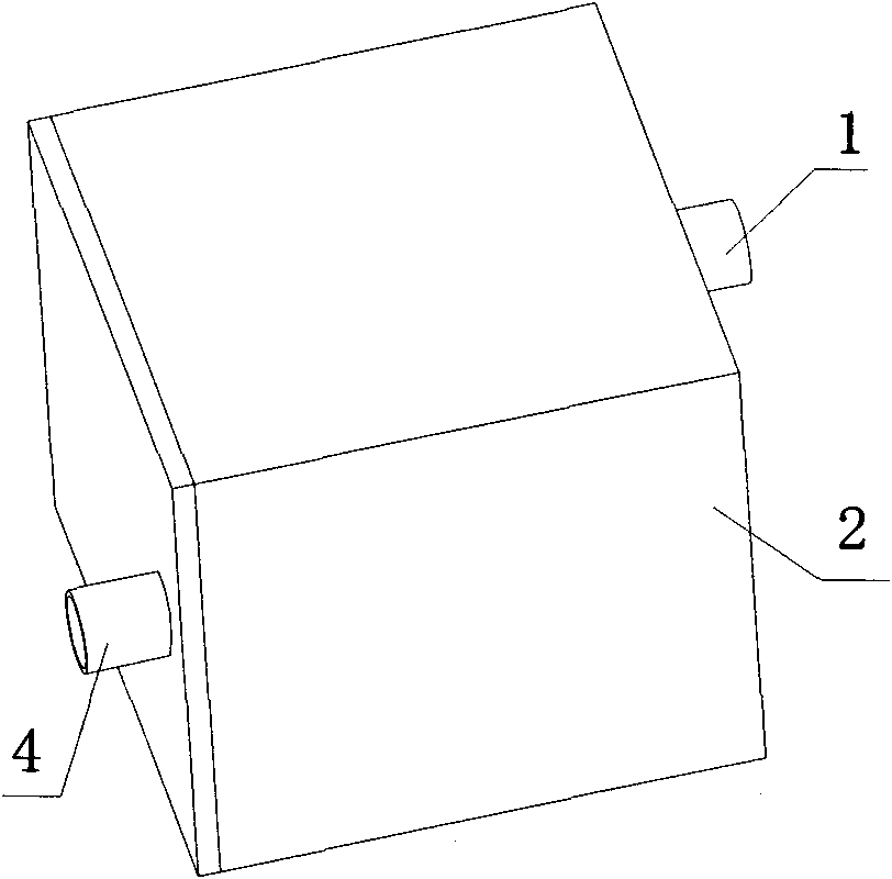
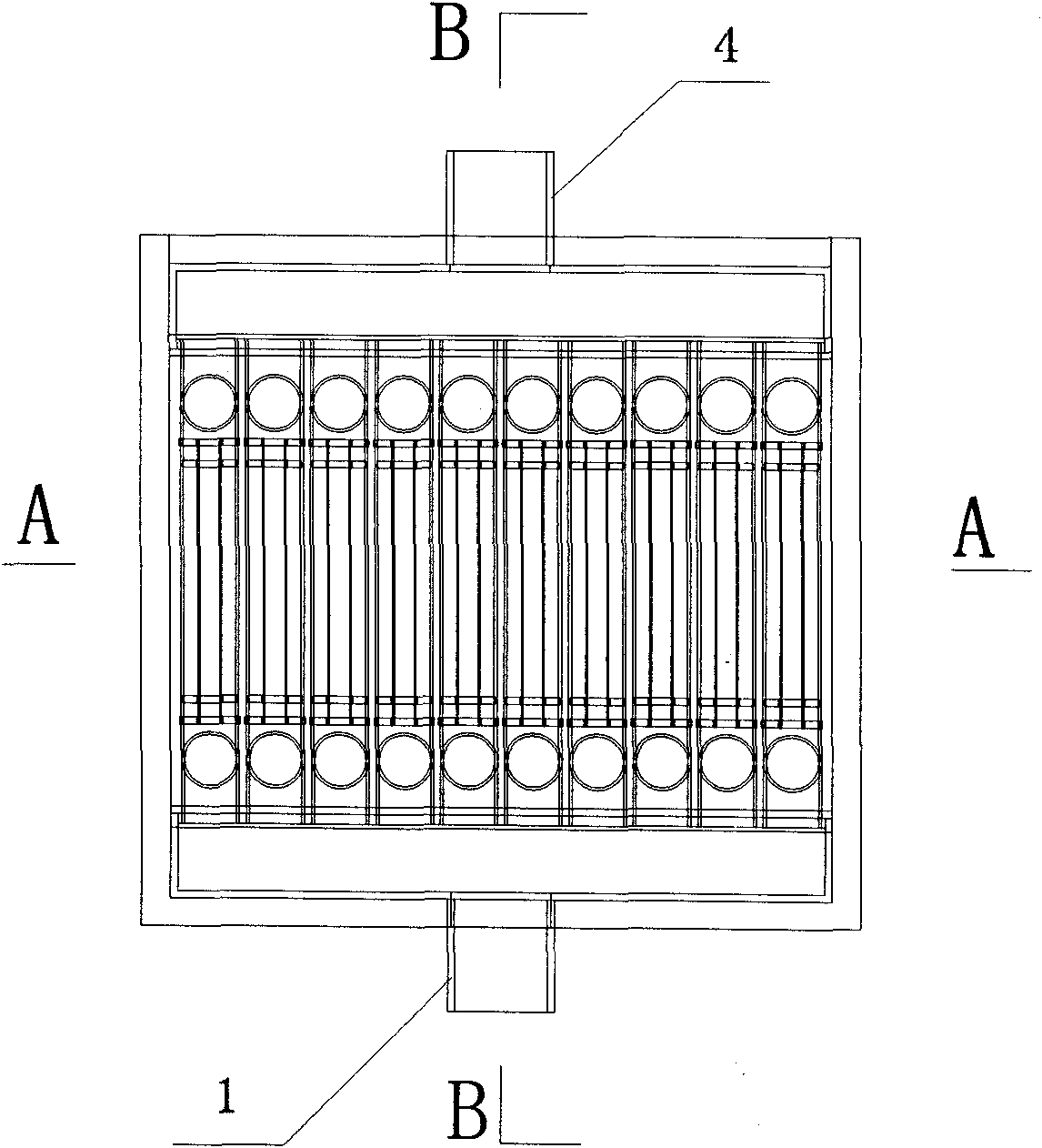
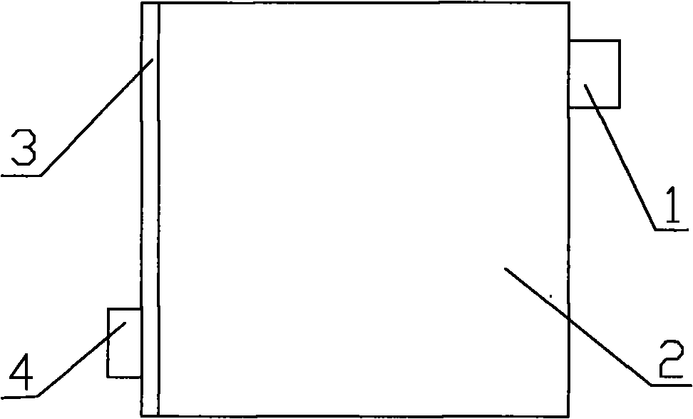
[0024] Such as figure 1 , figure 2 , image 3 , Figure 4 , Figure 5 , Image 6 As shown, a sleeve-type high-temperature heat storage device used in solar heat utilization includes an air inlet pipe 1, a heat storage chamber body 2, a heat storage chamber door 3, an air outlet pipe 4, a first ventilation cavity 5, The second ventilation cavity, heat storage material containing pipe 6, serpentine pipe, air circulation pipe connection plate 9, heat storage material containing pipe support 10, thermal insulation material, heat storage material;

[0025] The thermal storage chamber body 2 is composed of the outer wall of the thermal storage room and the inner wall of the thermal storage room. A sealed insulation cavity is formed between the outer wall of the thermal storage room and the inner wall of the thermal storage room. The thermal insulation cavity is filled with thermal insulation materials. It is a cube, and the outer wall of the heat storage room and the inner wall ...

Embodiment 2

[0041] Basically the same as Example 1, the difference is:

[0042] Al-Cu-Mg-Zn high-temperature phase change heat storage material, which is prepared from high-purity Al, Al-Cu master alloy, high-purity Mg and high-purity Zn raw materials, the mass percentage of each raw material is: high-purity Al 13 %, Al-Cu master alloy 52%, high-purity Mg 15%, high-purity Zn 20%;

[0043] The mass purity of the high-purity Al is ≥99.70%, the mass purity of the Al-Cu master alloy is ≥99.00%, the mass purity of the high-purity Mg is ≥99.50%, and the mass purity of the high-purity Zn is ≥99.50%.

[0044] The preparation method of the above-mentioned Al-Cu-Mg-Zn high-temperature phase change heat storage material (its preparation process is simple, only need to use the conventional aluminum-magnesium alloy smelting method), it includes the following steps:

[0045] 1) Ingredients: the mass percentage of each raw material is: high-purity Al 13%, Al-Cu master alloy 52%, high-purity Mg 15%, hig...


PUM


Abstract

The invention relates to a bushing-type high temperature heat storage device applied to solar heat utilization. The device is characterized by comprising an air inlet pipe, a heat storage room box body, a heat storage room door, an air outlet pipe, a first ventilation cavity, a second ventilation cavity, a heat storage material receiving pipeline, a coiled pipe, a heat storage material receiving pipeline support, a heat insulating material and a heat storage material, wherein the air inlet pipe is communicated with the first ventilation cavity positioned in heat storage space; the air outlet pipe is communicated with the second ventilation cavity positioned in the heat storage space; the coiled pipe is connected with a U-shaped pipe through an air flow pipeline; one end of the coiled pipe is communicated with the first ventilation cavity, and the other end of the coiled pipe is communicated with the second ventilation cavity; the heat storage material receiving pipeline is fixed with the air flow pipeline through the heat storage material receiving pipeline support; the heat storage material is encapsulated in the heat storage material receiving pipeline; and a heat transfer medium in the ventilation pipe is a gas. The bushing-type high temperature heat storage device has the advantages of simple structure, safety, reliability and high heat exchanging efficiency.

Description

technical field [0001] The invention relates to a sleeve-type high-temperature heat storage device applied to solar heat utilization. Background technique [0002] Solar energy utilization technology refers to the direct conversion and utilization technology of solar energy. Converting solar radiation energy into heat energy and utilizing it belongs to solar thermal utilization technology. Using the photovoltaic effect principle of semiconductor devices to convert solar energy into electrical energy is called solar photovoltaic technology. The history of human beings using solar energy can be traced back to 3000 years ago, but the history of actually using solar energy as a power and energy source is less than 400 years. [0003] my country's research on solar thermal power generation technology started relatively late, and some basic research did not start until the 1970s. The early research objects were mostly inorganic hydrated salts in phase change heat storage materia...

Claims


Application Information

Patent Timeline
Patent Type & Authority Applications(China)
IPC IPC(8): F24J2/46F24J2/34
CPCY02E10/40Y02P90/50
Inventor 程晓敏吴兴文张元杰谭永刚
Owner HUBEI KAIJIA ELECTRICAL TECH GROUP
Why Eureka
Try Eureka