Circuit and method for correcting direct current of active RC filter
A technology for calibrating circuits and filters, applied to networks using active components, electrical components, impedance networks, etc., can solve the problems of DC offset, the complex structure of the correction device of the zero-IF receiver, and the low DC correction efficiency. The effect of improving efficiency and simplifying structure
- Summary
- Abstract
- Description
- Claims
- Application Information
AI Technical Summary
Problems solved by technology
Method used
Image

Examples
Embodiment 1
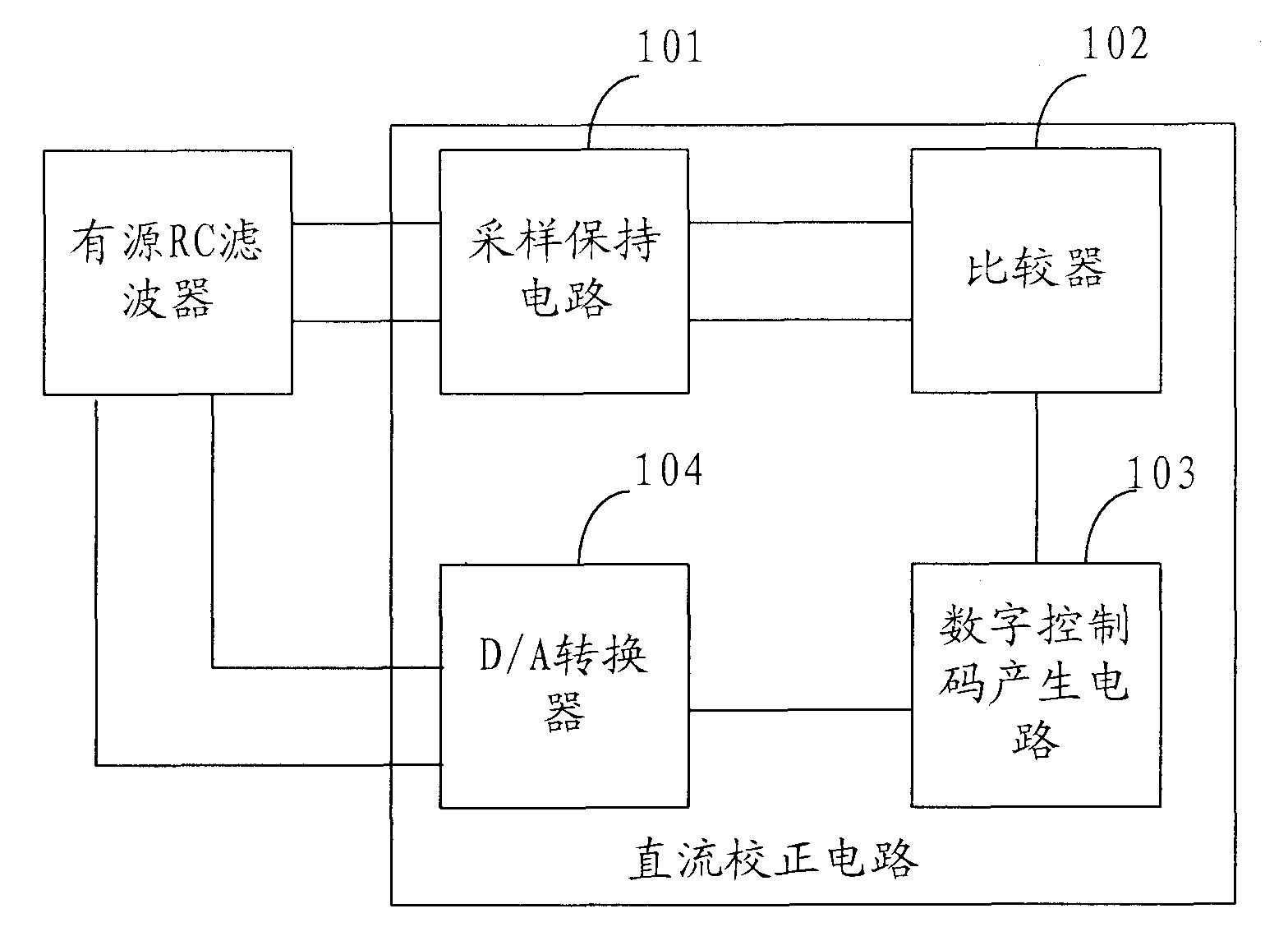
[0044] see figure 1 As shown, it is a schematic structural diagram of an active RC filter DC correction circuit provided by an embodiment of the present invention, the correction circuit includes: a sample and hold circuit 101, a comparator 102, a digital control code generation circuit 103 and a D / A converter 104;
[0045] The sample-and-hold circuit 101 is configured to sample the DC signals at the positive output terminal and the negative output terminal of the filter, and hold the sampled signal until the next sampling clock arrives;
[0046] The comparator 102 is used to compare the DC signals at the positive and negative output terminals of the filter obtained by sampling, and send the comparison result to the digital control code generation circuit 103;
[0047] The digital control code generation circuit 103 is used to generate a digital control code according to the comparison result;
[0048] The D / A converter 104 is used to convert the digital control code into an...
Embodiment 2
[0067] Compared with the active RC filter DC correction circuit described in Embodiment 1, the present invention also provides an active RC filter DC correction method, see Figure 4 Shown, is the schematic flow chart of this method, comprises the following steps:
[0068] Step S401: Sampling and holding the DC signals at the positive output terminal and the negative output terminal of the filter;
[0069] Step S402: Comparing the sampled DC signals at the positive and negative output terminals of the filter, and sending the comparison result to the digital control code generation circuit;
[0070] Step S403: generating a digital control code according to the comparison result;
[0071] Step S404: converting the digital control code into an analog control signal through a D / A converter;
[0072] Step S405: Send the analog control signal to the input end of the filter.
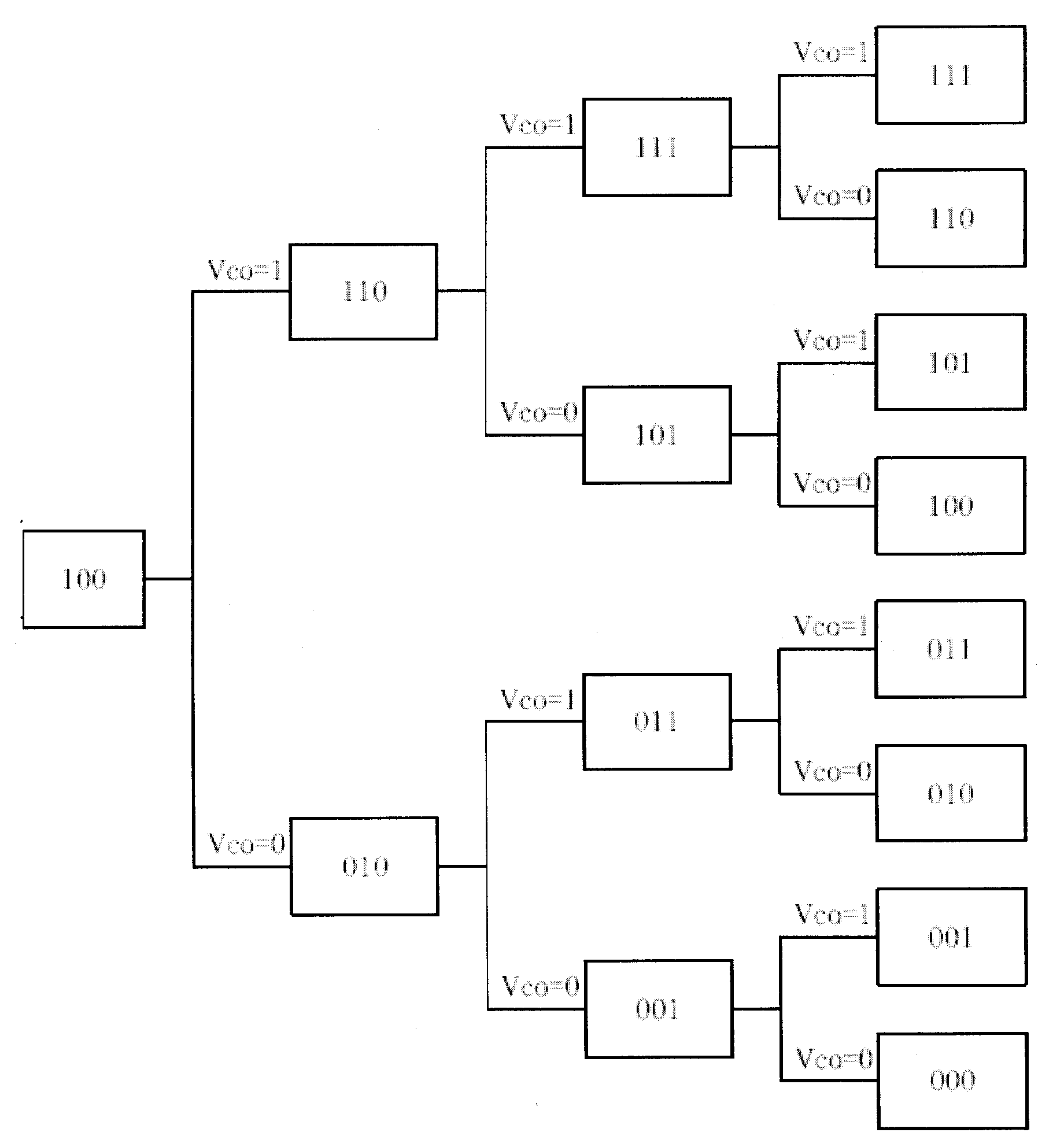
[0073] Wherein said generating digital control code according to said comparison result specifically incl...
PUM
 Abstract
Description
Claims
Application Information
 - R&D
- Intellectual Property
- Life Sciences
- Materials
- Tech Scout
- Unparalleled Data Quality
- Higher Quality Content
- 60% Fewer Hallucinations
Browse by: Latest US Patents, China's latest patents, Technical Efficacy Thesaurus, Application Domain, Technology Topic, Popular Technical Reports.
© 2025 PatSnap. All rights reserved.Legal|Privacy policy|Modern Slavery Act Transparency Statement|Sitemap|About US| Contact US: help@patsnap.com