Gas piston pulse engine

An engine and piston technology, applied in the field of gas piston pulse engines, can solve the problems of high manufacturing cost, complex structure, insufficient compression effect, etc., and achieve the effect of solving lubrication problems, less moving parts, and high compression ratio

Active Publication Date: 2010-09-08
无锡灵昌机械制造有限公司
View PDF5 Cites 8 Cited by
  • Summary
  • Abstract
  • Description
  • Claims
  • Application Information

AI Technical Summary

Problems solved by technology

However, whether the air is compressed by mechanical components such as a piston (such as a piston internal combustion engine) or a compressor (such as a gas turbine, jet engine, etc.), or the air is compressed by using the high-speed motion of the internal combustion engine to compress the air (such as a ram engine), there are very obvious disadvantages; the first two not only have complex structures and high manufacturing costs, but also need to lubricate the compressed air components such as pistons and turbines, which brings a series of problems, and the energy consumed by the compressed air itself comes from...

Method used


Image

  • Gas piston pulse engine
  • Gas piston pulse engine
  • Gas piston pulse engine

Examples


Embodiment 1

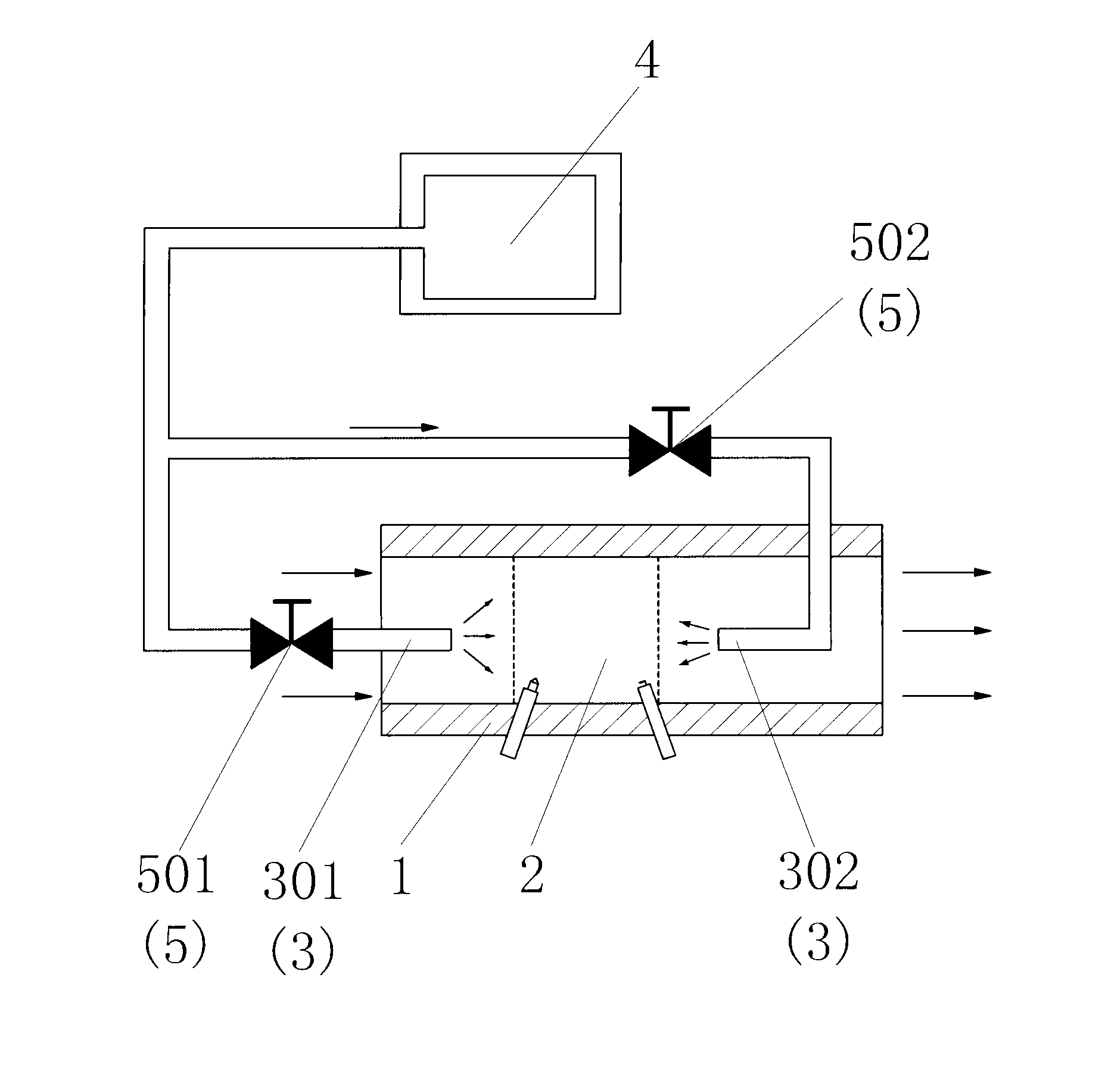
[0059] Such as figure 1 The gas piston pulse engine shown includes a nozzle 1, and a combustion chamber 2 is arranged in the nozzle 1; a forward high-pressure fluid nozzle 301 with the injection direction of the nozzle 1 as the overall injection direction is arranged in the nozzle 1, and the forward direction The high-pressure fluid nozzle 301 is arranged inside the cavity of the nozzle 1 on both sides of the combustion chamber 2, and the forward high-pressure fluid nozzle 301 communicates with the high-pressure fluid source 4 through the forward high-pressure fluid injection control valve 501; The opposite direction of the spraying direction of the nozzle 1 is the reverse high-pressure fluid nozzle 302 directed to the overall injection, and the reverse high-pressure fluid nozzle 302 is arranged inside the cavity of the nozzle 1 on both sides of the combustion chamber 2 . The reverse high-pressure fluid nozzle 302 communicates with the high-pressure fluid source 4 through the ...

Embodiment 2

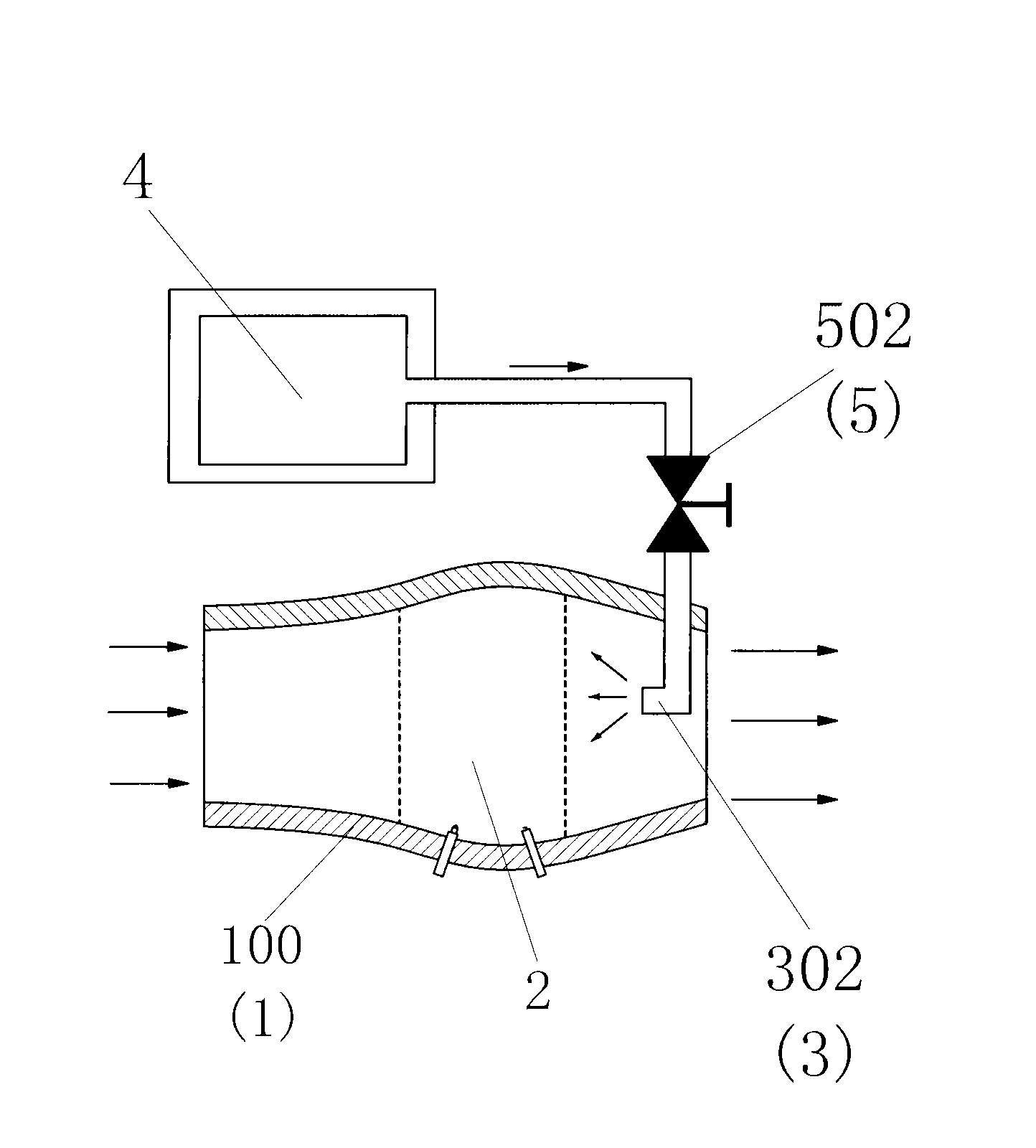
[0061] Such as figure 2 The gas piston pulse engine shown differs from Embodiment 1 in that only the reverse high-pressure fluid nozzle 302 with the reverse direction of the injection direction of the nozzle 1 as the overall injection direction is set in the nozzle pipe 1, and the reverse high-pressure fluid nozzle 302 It communicates with the high-pressure fluid source 4 through the reverse high-pressure fluid injection control valve 502 . High-pressure fluid nozzles 3 are arranged on the side walls of the nozzle pipe 1 on both sides of the combustion chamber 2 . The nozzle pipe 1 is designed as a partially pressurized nozzle pipe 100 with an expansion zone.

Embodiment 3

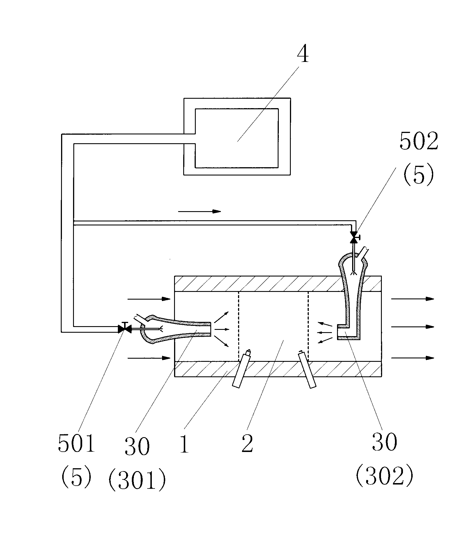
[0063] Such as image 3 The gas piston pulse engine shown differs from Embodiment 1 in that: the forward high-pressure fluid nozzle 301 and the reverse high-pressure fluid nozzle 302 are all set as the Venturi jet tube nozzle 30, and the high-pressure gas of the Venturi jet tube nozzle 30 The inlet communicates with a high-pressure fluid source 4 .


PUM


Abstract

The invention discloses a gas piston pulse engine comprising a spraying pipe (1). The spraying pipe (1) is internally provided with at least on combustion chamber (2); the inside and/or the side wall of the spraying pipe (1) are/is provided with at least one high-pressure fluid spraying nozzle (3) which takes the spraying direction of the spraying pipe (1) as the overall spraying direction and/orthe opposite spraying direction as the overall spraying direction; and the high-pressure fluid spraying nozzle (3) is communicated with a high-pressure fluid source (4) through a high-pressure fluid spraying controlling valve (5). The gas piston pulse engine has less motion parts and high compression ratio and solves the problems that the large numbers of motion parts of the prior combustion engine are difficult to lubricate and the pure ramjet engine can not be started in the static state and can not work in the low-speed working condition.

Description

technical field [0001] The invention relates to the field of engines, in particular to a gas piston pulse engine. technical background [0002] In the design of internal combustion engines, in order to make the mixture of fuel and air reach the high temperature and pressure required for the subsequent combustion and explosion, and to improve the thermal efficiency of the internal combustion engine, the intake air must be compressed. Three kinds of technical schemes are adopted in the existing internal combustion engine design to realize compressed air, that is, piston compressed air, turbine compressed air or ram compressed air. However, whether the air is compressed by mechanical components such as a piston (such as a piston internal combustion engine) or a compressor (such as a gas turbine, jet engine, etc.), or the air is compressed by using the high-speed motion of the internal combustion engine to compress the air (such as a ram engine), there are very obvious disadvan...

Claims


Application Information

Patent Timeline
IPC IPC(8): F02K7/02
Inventor 靳北彪
Owner 无锡灵昌机械制造有限公司
Why Eureka
Try Eureka