
Process and system for preparing ammonia from ammonium bicarbonate by using wet process for flue gas denitration

A technology of ammonium bicarbonate and ammonium bicarbonate solution, which is applied in separation methods, chemical instruments and methods, and dispersed particle separation, etc., can solve the problem of uneven feeding amount of ammonium bicarbonate, poor system operation stability, and easy fluctuation of ammonia gas volume. and other problems, to achieve the effect of easy control of the ammonia production process, prevention of crystallization in the tube, convenient and safe transportation and storage

Active Publication Date: 2010-09-15
ZHEJIANG GUANGHAN ENVIRONMENTAL PROTECTION TECH
View PDF6 Cites 26 Cited by
  • Summary
  • Abstract
  • Description
  • Claims
  • Application Information

AI Technical Summary

Problems solved by technology

The system is simple and economical, but it is found that the system has poor stability during operation, the feeding amount of ammonium bicarbonate is uneven, and the amount of ammonia gas is prone to fluctuations during the preparation process. The control of the system is relatively difficult, which affects the later stage. The effect of denitrification

Method used


Image

  • Process and system for preparing ammonia from ammonium bicarbonate by using wet process for flue gas denitration
  • Process and system for preparing ammonia from ammonium bicarbonate by using wet process for flue gas denitration
  • Process and system for preparing ammonia from ammonium bicarbonate by using wet process for flue gas denitration

Examples


Embodiment Construction

[0038] The present invention provides an ammonium bicarbonate wet ammonia production process for flue gas denitrification, and the present invention will be further described below with reference to the accompanying drawings and specific embodiments.

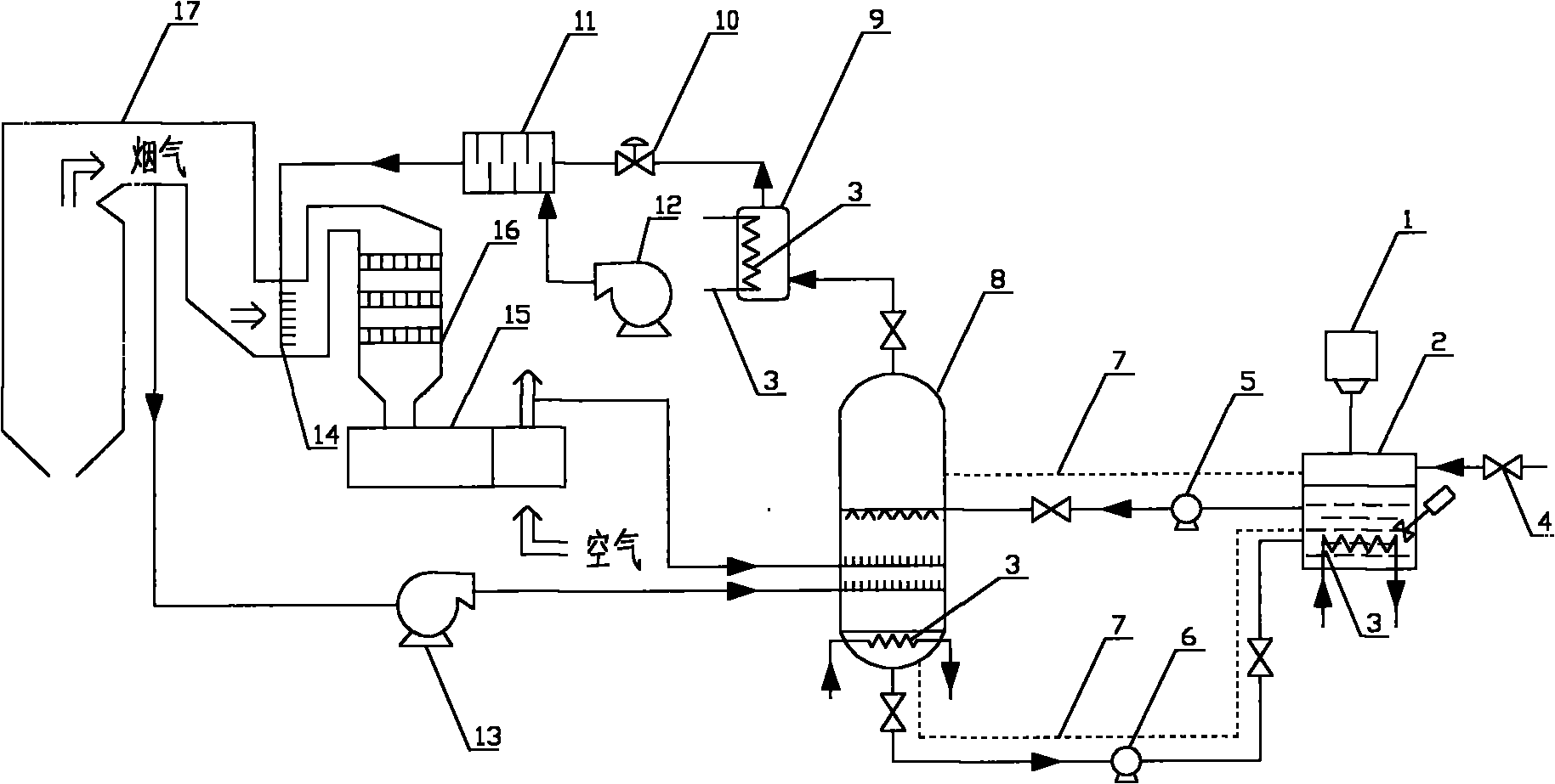
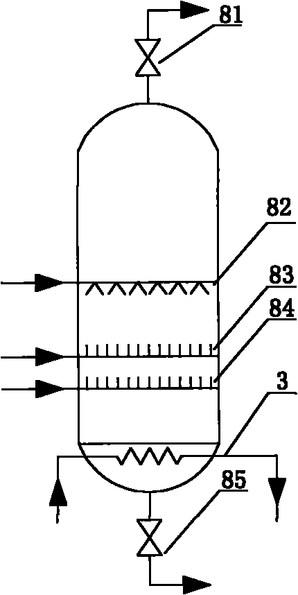
[0039] likefigure 1 As shown, the pyrolysis chamber 8 is a vertical round tank, the atomizing injection pipe 82 is arranged at the 3 / 5 elevation of the pyrolysis chamber, the high-temperature air introduction pipe 83 is arranged at the 1 / 3 elevation of the pyrolysis chamber, and the high-temperature flue gas The introduction pipe 84 is arranged at 1 / 4 elevation of the pyrolysis chamber. The outlet of the dissolution tank 2 is connected to the atomization injection pipe 82 at the upper part of the pyrolysis chamber 8 through a pipeline and a booster pump 5, and the high-temperature flue gas outlet of the boiler 17 is connected to the high-temperature flue gas at the lower part of the pyrolysis chamber 8 through a pipeline and a hi...


PUM


Abstract

The invention discloses a process and a system for preparing ammonia from ammonium bicarbonate by using a wet process for flue gas denitration, belonging to the technical field of flue gas denitration in a thermal power plant. In the process, an ammonium bicarbonate solution at 90 DEG C is boosted and then enters an atomizing nozzle of a pyrolyzing furnace for backflow ejection, fogdrop of the ammonium bicarbonate decompose out ammonia gas under the heating action of high-temperature flue gas flowing from bottom to top, and the residual ammonium bicarbonate solution converges at the bottom of the pyrolyzing furnace and then returns to a dissolution pool through a circulating pump for recycling; and the ammonia gas flows to a buffer tank together with air, enters an ammonia gas-air mixer and then enters an SCR (Selective Catalyst Reduction) reactor through an ammonia-spraying grating after being diluted to certain concentration, and in the presence of a catalyst, the ammonia gas reduces NOX into N2. The ammonium bicarbonate is a reducing agent which is convenient and safe to transport and store, has better economy than urea and avoids the potential safety hazard of the reducing agents of liquid ammonia, ammonia water and the like in the aspects of transportation and storage. By adopting the ammonium bicarbonate as the reducing agent to pyrolyze for preparing the ammonia with the wet process, the whole system has the advantages of easy dosage control of the ammonium bicarbonate, stable ammonia gas generation, simplicity and high efficiency.

Description

technical field [0001] The invention belongs to the technical field of flue gas denitrification in thermal power plants, and in particular relates to an ammonium bicarbonate wet ammonia production process and system for flue gas denitrification. Background technique [0002] The flue gas emitted by thermal power plants contains NO x , seriously pollute the environment. The increasingly stringent environmental regulations require that new thermal power generating units must be equipped with a denitrification system. The commonly used flue gas denitrification technology is generally to prepare ammonia gas from the denitrification reducing agent, and then spray the ammonia gas into the flue gas through the ammonia injection grid. Under the action of catalyst, NO x reduced to N by ammonia gas 2 . [0003] The commonly used reducing agents in the flue gas denitrification system of thermal power plants are liquid ammonia, ammonia water and urea. Liquid ammonia is highly toxi...

Claims


Application Information

Patent Timeline
Patent Type & Authority Applications(China)
IPC IPC(8): B01D53/76B01D53/86B01D53/56
Inventor 叶力平翁卫国
Owner ZHEJIANG GUANGHAN ENVIRONMENTAL PROTECTION TECH
Learn More