
Process for improving metallographic structure of piston head and increasing casting production efficiency

A metallographic structure and casting production technology, applied in the direction of manufacturing tools, casting molding equipment, metal processing equipment, etc., can solve the problems of low production efficiency, large difference in piston hardness, long feeding time, etc., to improve the utilization of materials. rate, improve cooling effect, shorten the effect of feeding time

Active Publication Date: 2010-09-15
CHENGDU GALAXY POWER CO LTD
View PDF3 Cites 7 Cited by
  • Summary
  • Abstract
  • Description
  • Claims
  • Application Information

AI Technical Summary

Problems solved by technology

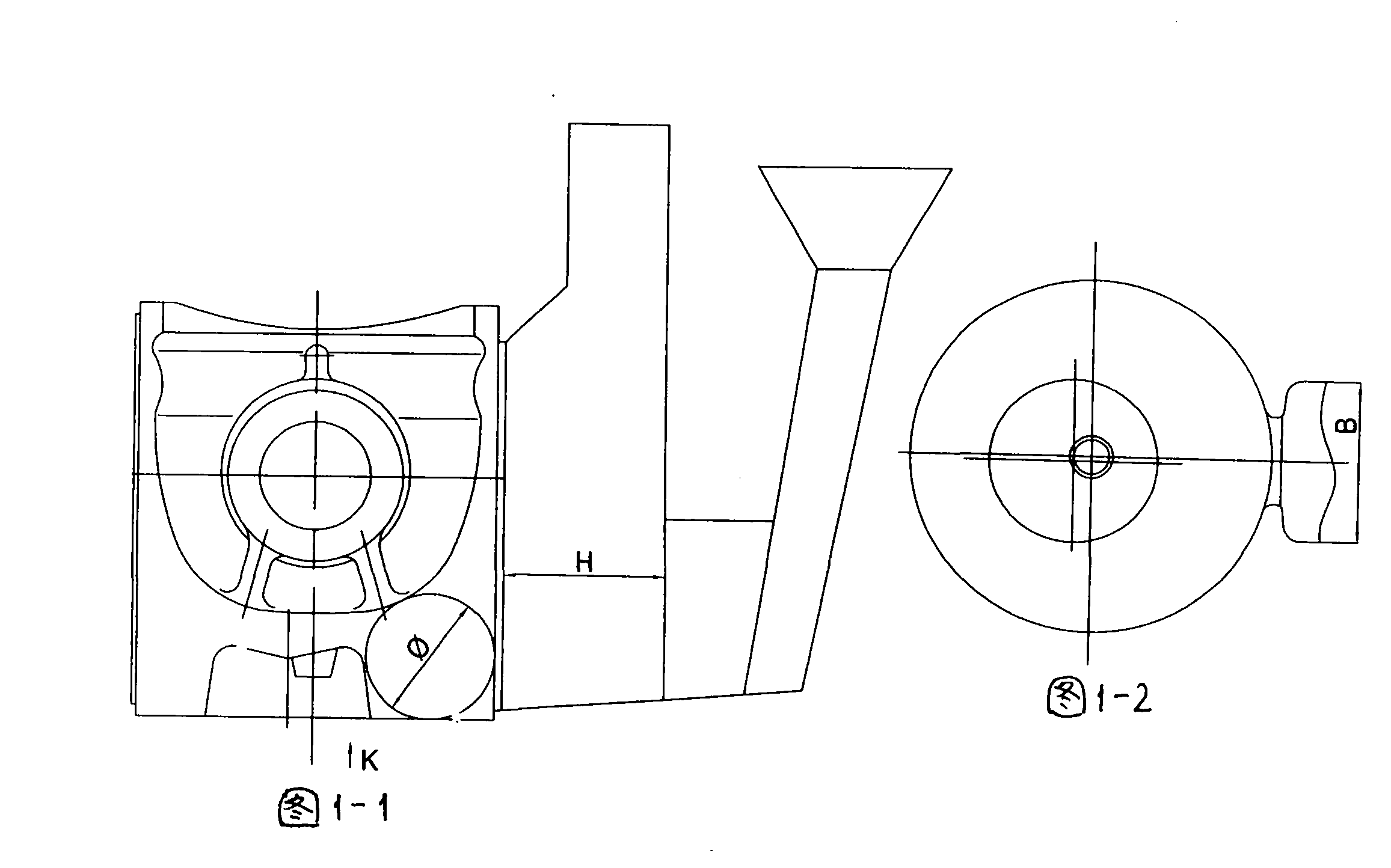
[0002] Most of the ordinary piston casting blanks are cast by gravity casting with core pulling. The cost is high, so at present, the outer mold of piston forming generally adopts a single-side riser structure, and the position of the single-side riser is usually designed on the side with a large thermal pitch circle of the piston body, so as to facilitate the feeding of the piston blank by the heat preservation riser; The bottom mold adopts a structure with vent holes and is forced to cool with water at the same time, but the cooling distance is relatively long, reaching 16-20mm, and the cooling effect is relatively poor
With the above structure, the metallographic structure of the piston is generally at level 2-3, and the primary crystal silicon at the head is at 20-30 microns; the feeding time is long, the worker pauses for a long time, and the production efficiency is generally not high; after the piston blank is demoulded, the overall The temperature uniformity is poor, and the overall hardness difference of the piston after casting and quenching is relatively large

Method used


Image

  • Process for improving metallographic structure of piston head and increasing casting production efficiency
  • Process for improving metallographic structure of piston head and increasing casting production efficiency
  • Process for improving metallographic structure of piston head and increasing casting production efficiency

Examples


Embodiment Construction

[0038] This process technology is specifically implemented on the eutectic Al-Si alloy piston, and the specific variety is 495T;

[0039] In order to ensure the accuracy of the experiment, it is necessary to monitor all aspects of design and production. The process is as follows:

[0040] 1. Tooling and mold design: Design tooling and molds according to the technical content, principle and effect analysis of this process.

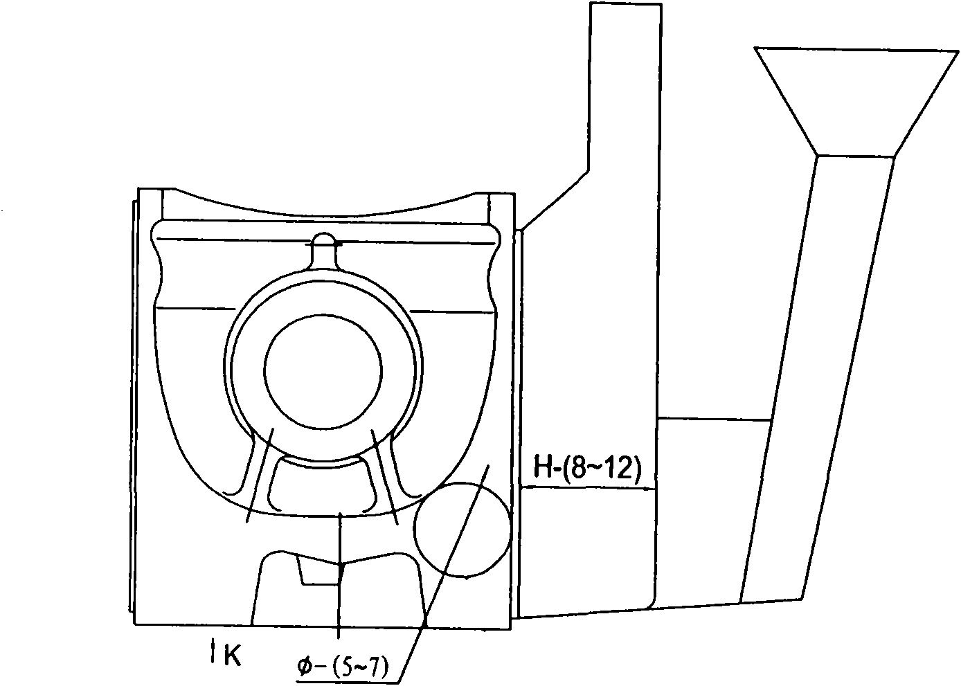
[0041]a) Change the traditional design of the eccentricity of the long axis of the piston combustion chamber in the past, and make the eccentricity of the long axis of the piston combustion chamber in the front, so that the diameter of the thermal pitch circle in the direction of the piston riser is reduced by 5-7mm, corresponding to 495T, YC6108G, LR105, N485, N485AW, RCB108, LR108-1 series engine pistons, the diameters before modification are 30mm, 35mm, 31mm, 27.5mm, 27.5mm, 33.5mm, 33.5mm; Possibility, and shorten the feeding time, and at the same time...


PUM


Abstract

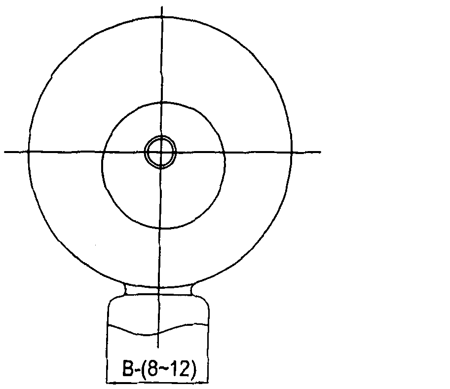
The invention provides a process for improving the metallographic structure of a piston head and increasing casting production efficiency. The process comprises the steps of: (1) eliminating an exhaust hole and an exhaust nail on a bottom die, and meanwhile reducing the thickness of a wall between the bottom die and a cooling water cavity, respectively subtracting 10mm from the length and the width of a casting head on an outer die, wherein the specifications of the length and the width are respectively 48mm-55mm and 48mm-54mm; and meanwhile, adding 10mm-12mm to the length L2 of the rear part of the outer die, and adding 5mm-8mm to the width D of the rear part of the outer die, wherein the specifications of the length L2 and the width D are respectively 176-mm-195mm and 78mm-85mm; (2) processing a tooling die; (3) preparing for the smelting of an aluminum liquid; (4) assembling and debugging the tooling die; (5) casting in field production; (6) hot treating a piston blank; and (7) detecting the quality of the piston. The invention can refine the metallographic structure of the piston head by 1-2 levels and improve casting efficiency by more than 15%.

Description

technical field [0001] The process technology relates to a casting process method for aluminum alloy casting parts, especially a casting process method for producing an upper core-pulling aluminum alloy piston. Background technique [0002] Most of the ordinary piston casting blanks are cast by gravity casting with core pulling. The cost is high, so at present, the outer mold of piston forming generally adopts a single-side riser structure, and the position of the single-side riser is usually designed on the side with a large thermal pitch circle of the piston body, so as to facilitate the feeding of the piston blank by the heat preservation riser; The bottom mold adopts a structure with vent holes and is forced to cool with water at the same time, but the cooling distance is relatively long, reaching 16-20mm, and the cooling effect is relatively poor. With the above structure, the metallographic structure of the piston is generally at level 2-3, and the primary crystal sil...

Claims


Application Information

Patent Timeline
IPC IPC(8): B22C9/08B22D21/04B22D27/04
Inventor 杨庆年彭明诚何光驰文均陈革
Owner CHENGDU GALAXY POWER CO LTD
Learn More