Saw plate positioning device for gang saw welder

A positioning device and welding machine technology, applied in the field of machinery, can solve the problems of inaccurate welding saw teeth, reduce production efficiency, increase spacing, etc., and achieve the effects of ensuring accuracy and pressing force, improving stability, and avoiding shaking

Active Publication Date: 2010-09-15
项大清
View PDF6 Cites 12 Cited by
  • Summary
  • Abstract
  • Description
  • Claims
  • Application Information

AI Technical Summary

Problems solved by technology

It can be seen that the time required for cooling increases the time required for welding and reduces production efficiency; the deformation of the saw board reduces the accuracy of the next welding point
Furthermore, since the distance between the pressing surface of the clamping block 1 and the pressing surface of the clamping block 2 is relatively large, the sawing board will swing and rub against the clamping block 1 and the clamping block 2 during the process of moving the sawing board. Both the clamping block 1 and the clamping block 2 are made of copper material, and the surface of the saw board is relatively rough, so that the saw board wears the clamping block 1, causing the distance between the pressure surface of the clamping block 1 and the welding head to increase. Large size leads to inaccurate welding saw teeth; the saw board wears the clamping block 2, resulting in an increase in the distance between the pressing surface of the clamping block 2 and the pressing surface of the clamping block 1, resulting in insufficient clamping force
At the same time, there is still motion instability in the process of moving the saw board, which reduces the accuracy of reaching the next welding point

Method used


Image

  • Saw plate positioning device for gang saw welder
  • Saw plate positioning device for gang saw welder
  • Saw plate positioning device for gang saw welder

Examples


Embodiment 1

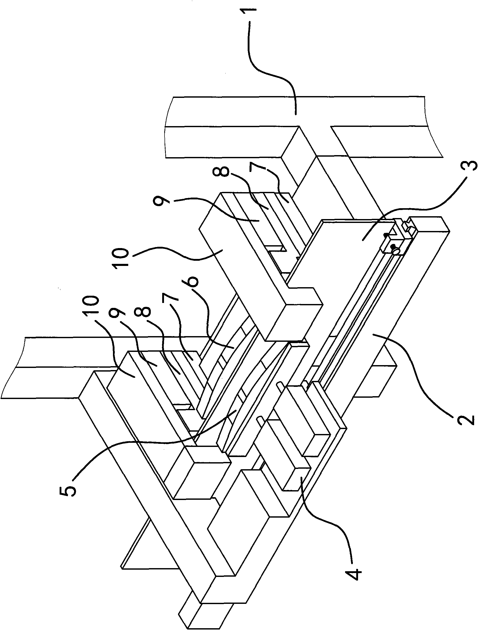
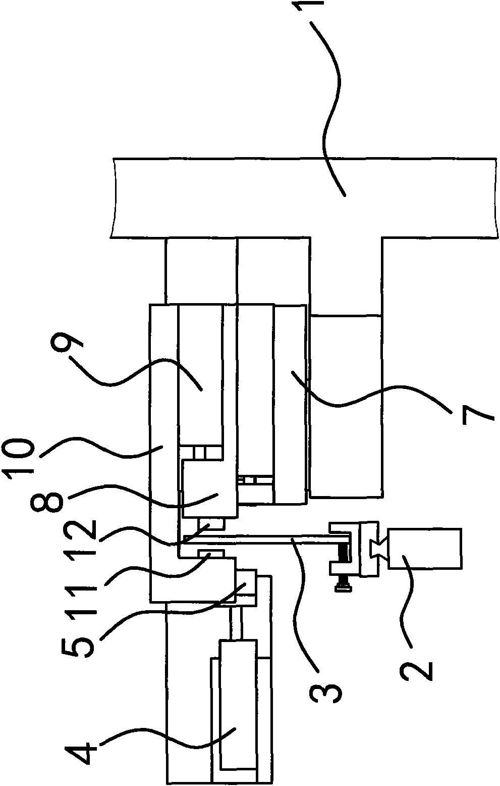
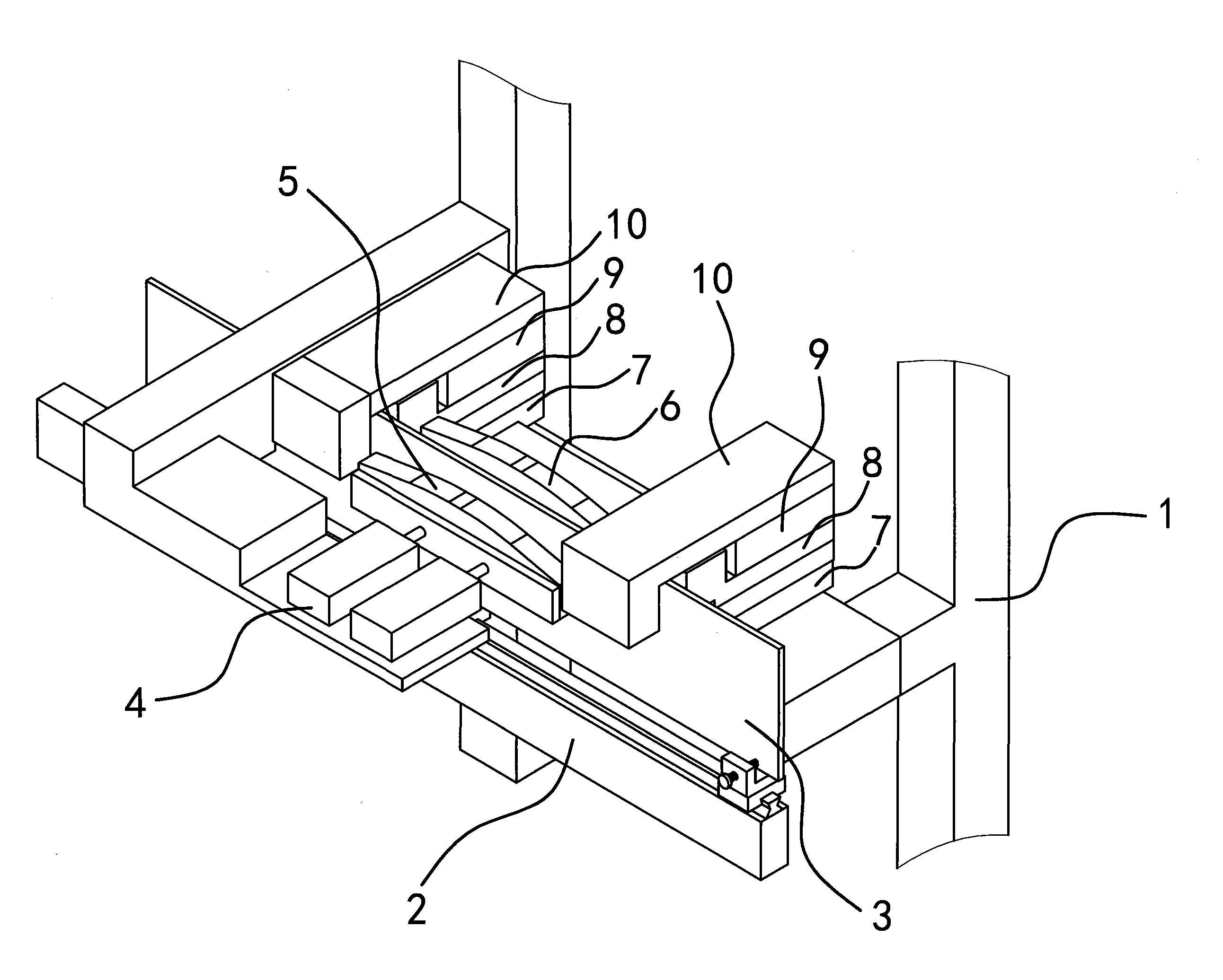
[0028] Specifically, as figure 1 and figure 2 As shown, the clamping block one 6 is fixed on the frame 1 and is positioned at the inner side of the saw board 3, the clamping block two 5 and the cylinder one 4 are arranged on the outside of the saw board 3, and the cylinder body of the cylinder one 4 is fixed on the frame 1, the clamping block two 5 is fixed on the piston rod of the cylinder one 4. The pressing surface of the clamping block one 6 is opposite to the pressing surface of the clamping block. The saw board 3 is located between the clamping block one 6 and the clamping block two 5. Clamping block two 5 moves towards the direction close to clamping block one 6, and sawing board 3 is clamped and fixed under the joint action of clamping block one 6 and clamping block two 5.

[0029] Guide piece one 11 and guide piece two 12 are guide rollers, and this guide roller directly replaces with bearing. Both sides of the clamping block 6 are provided with a guide 11; the el...

Embodiment 2

[0040] The structure and principle of this embodiment are basically the same as that of Embodiment 1, the difference is that the elastic mechanism includes a guide rod 1 and a fixed seat 8, the guide rod 1 is fixed on the frame 1, and the fixed seat 8 is slidably connected to the guide rod 1. On the rod one, the above-mentioned guide part one 11 is arranged on the fixed seat one 8, and a guide bar is provided between the guide rod one and the fixed seat one 8 so that the guiding surface of the guide part one 11 to the guide part one 11 is always close to the clamping block two. Move spring one in the direction of the pressing surface of 5. The cylinder block of cylinder three 9 is fixed on the holder one 8 in the driving mechanism.

Embodiment 3

[0042] The structure and principle of this embodiment are basically the same as that of Embodiment 1, the difference is that the drive mechanism includes guide rod two, fixed seat two 10, the guide rod two is fixed on the fixed seat one 8, and the fixed seat two 10 is slidably connected to the guide On the rod two, the above-mentioned guide member two 12 is arranged on the second fixing seat 10, and a spring two is arranged between the second guide rod and the second fixing seat 10.


PUM


Abstract

The invention provides a saw plate positioning device for a gang saw welder, which belongs to the technical field of machinery and solves the problem that two sides of a clamping block in the conventional gang saw welder have no positioning devices, so a saw plate is easy to deform when the heated hardness is reduced, the motion is instable during moving the saw plate and the precision of a next welding point is reduced. The saw plate positioning device for the gang saw welder comprises a first clamping block and a second clamping block; the first clamping block is fixed on a rack; the second clamping block is arranged on the rack through an air cylinder, and the propped faces of the second clamping block and the rack are arranged opposite; the positioning device also comprises a first guide piece; and an elastic mechanism, which enables the first guide piece to move in the direction of the guide face of the first guide piece close to the propped face of the second clamping block when the first clamping block and the second clamping block are loosened from the saw plate, is arranged on the rack. The saw plate positioning device for the gang saw welder can ensure the accuracy of welding saw teeth, avoid deformation and improve the production efficiency, and has the advantage of stable performance.

Description

technical field [0001] The invention belongs to the technical field of machinery, and relates to a welding machine, in particular to a saw board positioning device of a gang saw welding machine. Background technique [0002] Diamond gang saw is a relatively advanced new tool for cutting marble stone at will. The main motor of the gang saw machine drives the flywheel, which drives the saw frame to do linear reciprocating motion; the block cart loaded with blocks is lifted by the lifting platform to realize block lifting sawing. When processing blocks, the saw frame keeps moving back and forth, and the block cart loaded with blocks rises along the guiding mechanism, which can greatly improve the cutting effect. [0003] The gang saw consists of a saw board and diamond teeth fixed on the saw board. Chinese patent literature once disclosed a thin-walled base material welding device [Chinese Patent No.: 200820038094.1; authorized announcement number CN201211601Y], including a w...

Claims


Application Information

Patent Timeline
Patent Type & Authority Applications(China)
IPC IPC(8): B23K37/04B23K37/053
Inventor 项大清
Owner 项大清
Why Eureka
Try Eureka