System and method for removing phosphorus by three-mud process nitrification and denitrification

A denitrification phosphorus removal and treatment system technology, applied in the field of urban sewage treatment, can solve the problems of large area, high phosphorus content in sludge, ammonia nitrogen cannot meet high discharge standards, etc., to reduce infrastructure and operating costs, improve The effect of nitrogen and phosphorus removal, the effect of overcoming the slow rate of nitrification

Active Publication Date: 2010-09-15
深圳市慧创源环保科技有限公司
View PDF5 Cites 19 Cited by
  • Summary
  • Abstract
  • Description
  • Claims
  • Application Information

AI Technical Summary

Problems solved by technology

These processes have the advantages of the double sludge method, but for urban sewage with high concentrations of total nitrogen and ammonia nitrogen and low concentrations of organic matter in southern my country, these processes still have deficiencies when reaching the first-class A effluent standard
(1) Since the ammonia nitrogen carried by the excess sludge cannot be removed in the subsequent treatment unit, when the total nitrogen in the influent exceeds 25mg / L, the ammonia nitrogen in the effluent of the existing double sludge method cannot meet the high discharge standard of Class A, and most Municipal sewage plant raw water is usually higher than this total nitrogen concentration
(2) The phosphorus content of the sludge in the secondary sedimentation tank is high, and the phosphorus content of the sludge is usually higher than that of conventional A 2 / O, so even if a small amount of sludge flows out with the supernatant, it is very easy to cause the total phosphorus in the effluent to exceed the standard. Therefore, the total phosphorus in the effluent of the existing double-sludge method cannot stably meet the standard
(3) The colloids and particulate organic matter in the raw water are mixed with the sludge in the anaerobic tank and the secondary sedimentation tank, and enter the anoxic tank with the sludge. In the existing double-sludge process, these colloids and particulate organic matter exist in the form of carbon sources other than carbon sources , which is not conducive to the operation of the process. First, microorganisms can use this part of the external carbon source for denitrification but cannot absorb phosphorus, resulting in the carbon source not being able to "one carbon for two purposes". Second, due to insufficient hydrolysis, particulate organic matter may The mixed liquid in the anoxic tank enters the secondary settling tank, resulting in the release of phosphorus in the secondary settling tank, and the effluent exceeds the standard; (4) the existing double-sludge method usually uses the conventional contact oxidation method as the nitrification tank, which occupies a large area, and the double-sludge method is larger than the conventional one. A 2 The / O method has an additional sedimentation tank, so the contact oxidation tank with too large area is not suitable for urban areas with tight land use
(5) In order to ensure the high sedimentation efficiency of the secondary sedimentation tank, the existing double mud method must adopt a lower surface load (for example, 0.5 ~ 0.8m 3 / m 2 / h), resulting in a large area occupied by the secondary settling tank

Method used


Image

  • System and method for removing phosphorus by three-mud process nitrification and denitrification
  • System and method for removing phosphorus by three-mud process nitrification and denitrification
  • System and method for removing phosphorus by three-mud process nitrification and denitrification

Examples


Embodiment Construction

[0052] The technical solution of the present invention will be described in detail below in conjunction with the accompanying drawings.

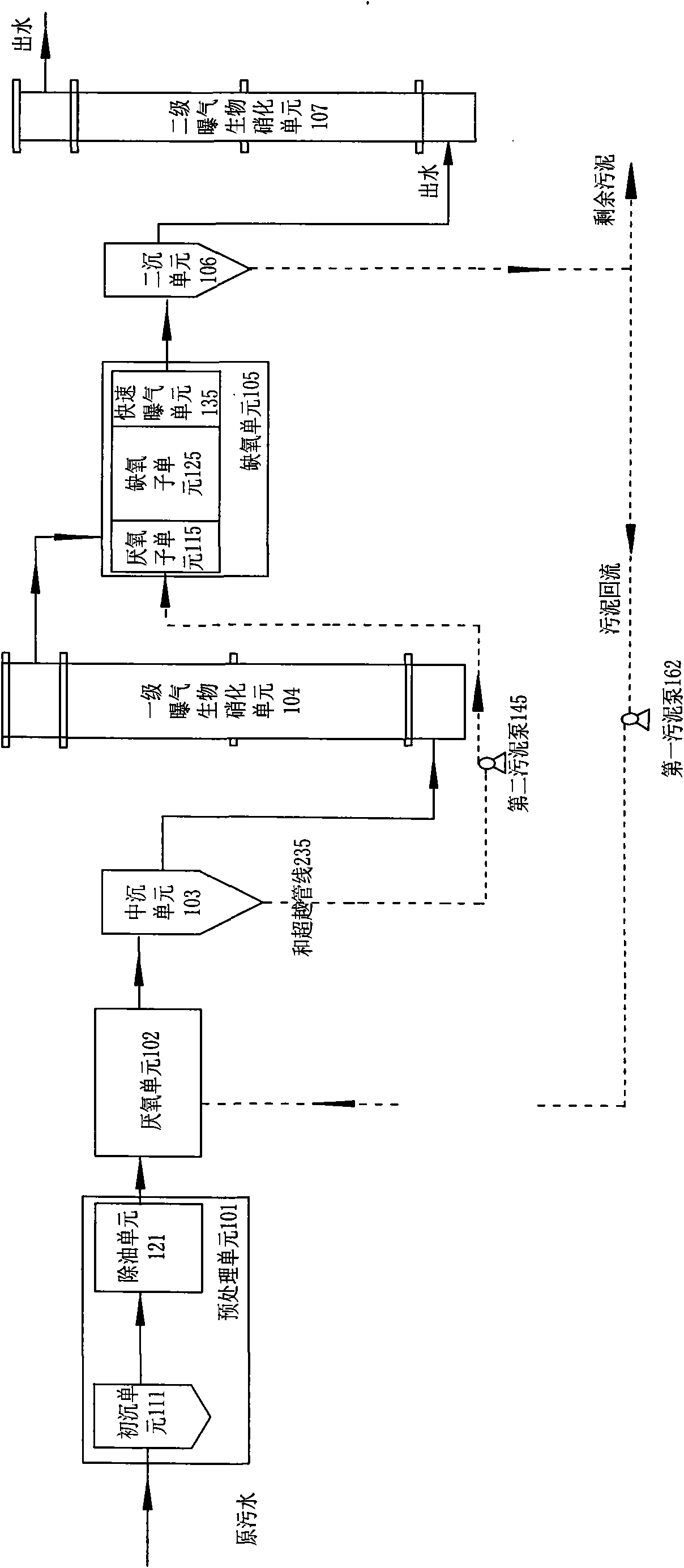
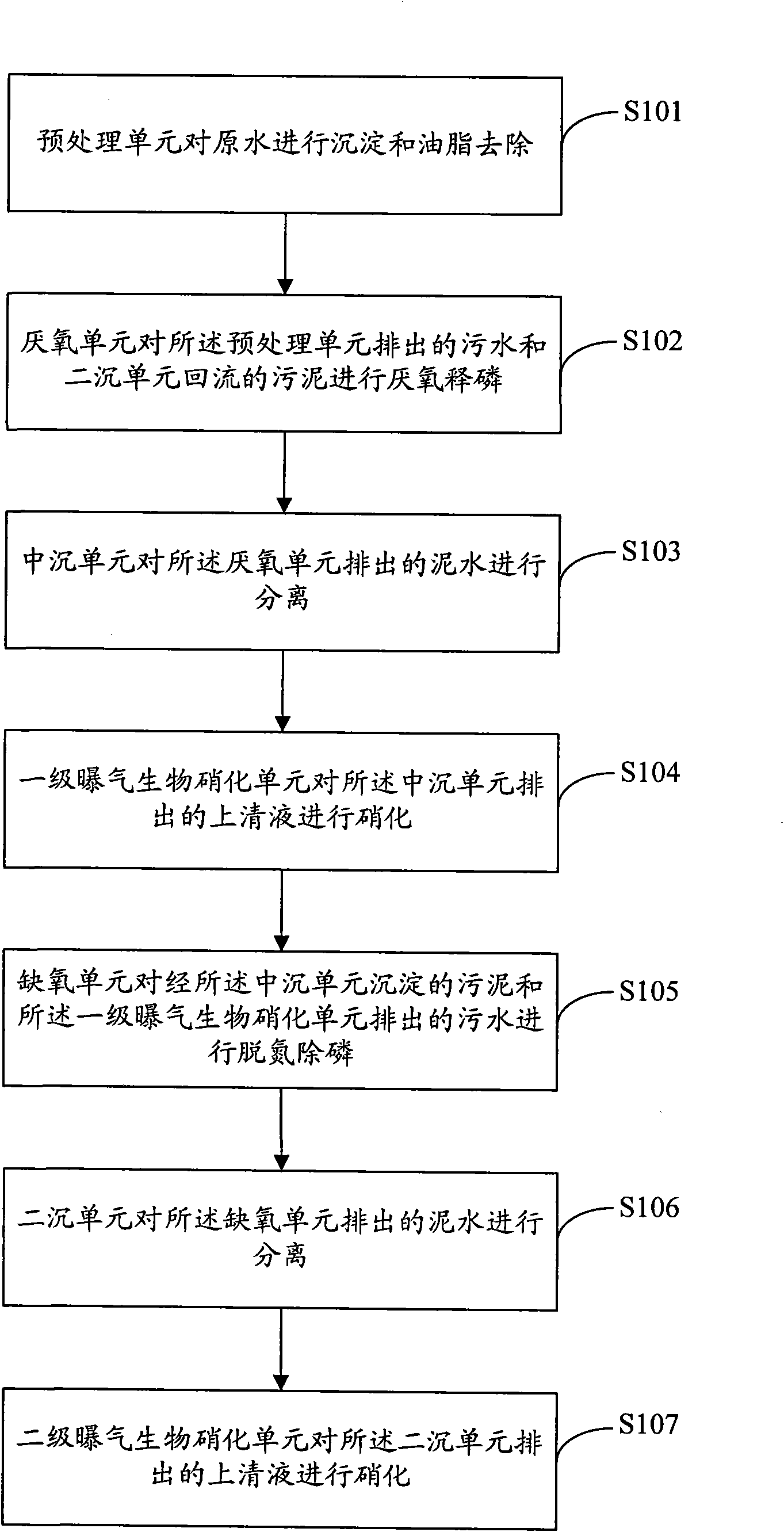
[0053] figure 1 It is a structural schematic diagram of the nitrification and denitrification phosphorus removal treatment system of the present invention. Such as figure 1 As shown, the three-sludge method nitrification and denitrification phosphorus removal treatment system includes a pretreatment unit 101, anaerobic unit 102, middle sink unit 103, primary aeration biological nitrification unit 104, anoxic unit 105, secondary sink unit 106 and two Stage aerated biological nitrification unit 107.

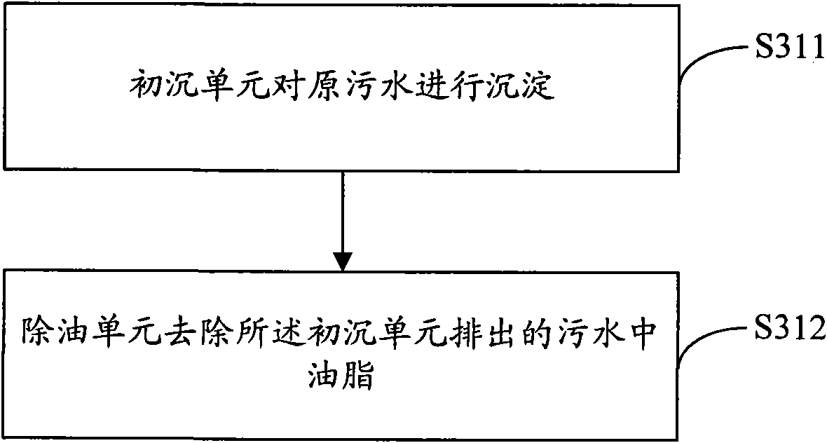
[0054] The pretreatment unit 101 is used for precipitating raw water and removing grease. In a preferred technical solution of the present invention, the pretreatment unit 101 specifically includes a primary sedimentation unit 111 and an oil removal unit 121 . Wherein, the primary sedimentation unit 111 precipitates the raw water. The sewage...


PUM

PropertyMeasurementUnit
surface load factoraaaaaaaaaa

Abstract

The invention relates to a system and a method for removing phosphorus by three-mud process nitrification and denitrification. The system comprises a pretreating unit, an anaerobic unit, a middle precipitation unit, a primary aeration biological nitrification unit, an anoxic unit, a secondary precipitation unit and a secondary aeration biological nitrification unit. The method comprises the following steps that: after being precipitated in the pretreating unit for removing oil, the primary water enters an anaerobic pool with returned sludge to anaerobicly release the phosphorus; microorganisms absorb polyhydroxyrate (PHB) in a dissoluble organic compound body in the water; after muddy water is precipitated in a middle precipitation pool, a supernatant enters the primary aeration biological nitrification unit and an effluent and sludge in the middle precipitation pool enter an anaerobic pool to undergo denitrification and dephosphorization; and after mixed solution in the anaerobic pool is separated in a secondary precipitation pool, the supernatant enters the secondary aeration biological nitrification unit for further treatment, wherein one part of the sludge is reclaimed and theother parts of the sludge are discharged as remaining sludge. The system of the invention is small in occupied area and low in basic construction and operation costs. For low-carbon and nitrogen urban sewage, the effluent of the system can stably meet the first grade A standards of Urban Sewage Disposal Plant Contamination Integrated Discharge Standard.

Description

【Technical field】 [0001] The technical solution of the invention belongs to the field of urban sewage treatment with a medium-low carbon-to-nitrogen ratio (COD / TN is between 3 and 10), and specifically relates to a three-sludge nitrification and denitrification phosphorus removal treatment system and method. 【Background technique】 [0002] According to the first grade A of the "Pollutant Discharge Standard for Urban Sewage Treatment Plants GB18918-2002", after the urban sewage is treated, the discharged sewage must meet the requirements of TN≤15mg / L, NH 4 + -N≤5mg / L, TP≤0.5mg / L. Therefore, how to reduce the NH in the discharged sewage while removing the organic matter in the sewage 4 + The content of -N, TN and TP has become one of the urgent tasks facing the technology of sewage treatment. Nitrogen and phosphorus have become the biggest problems for new sewage plants and upgrading of old plants. Urban sewage in southern my country generally has the characteristics of l...

Claims


Application Information

Patent Timeline
Patent Type & Authority Applications(China)
IPC IPC(8): C02F9/14C02F3/30
Inventor 李继董文艺吕小梅廖凤京
Owner 深圳市慧创源环保科技有限公司
Why Eureka
Try Eureka