
Cylindrical plastic methane generator

A biogas generator and plastic technology, used in gas production bioreactors, biochemical instruments, waste fuels, etc., can solve problems such as leakage, insufficient hardness, and low pressure.

Active Publication Date: 2010-09-15
保定广釜塑料制品有限公司
View PDF2 Cites 3 Cited by
  • Summary
  • Abstract
  • Description
  • Claims
  • Application Information

AI Technical Summary

Problems solved by technology

[0002] Most of the existing plastic biogas generators are spherical or ellipsoidal, and are composed of multiple fan-shaped tiles. Generally, the volume of the biogas generator formed by splicing is fixed, and the existing fan-shaped tiles cannot be spliced ​​according to specific needs. For different biogas generators, the specific specifications of the fan-shaped tiles required for injection molding are different, the required molds will also increase, and the cost is high; and welding or riveting is generally used between two fan-shaped adjacent tiles, and the sealed gas The tightness is poor, the internal pressure of the container is low, the welding process has high requirements for raw materials, and the cost is high, the strength is low, and the hardness is not enough. After the weld is broken, people need to repair the welding in the container, which is difficult to repair ;When riveting, one end of the rivet will pass through the inner surface of the spherical container, and the material in the spherical container will be exposed to corrosion for a long time, causing leakage and affecting the service life

Method used


Image

  • Cylindrical plastic methane generator
  • Cylindrical plastic methane generator
  • Cylindrical plastic methane generator

Examples


Embodiment Construction

[0031] The present invention will be described in further detail below in conjunction with the accompanying drawings and embodiments.

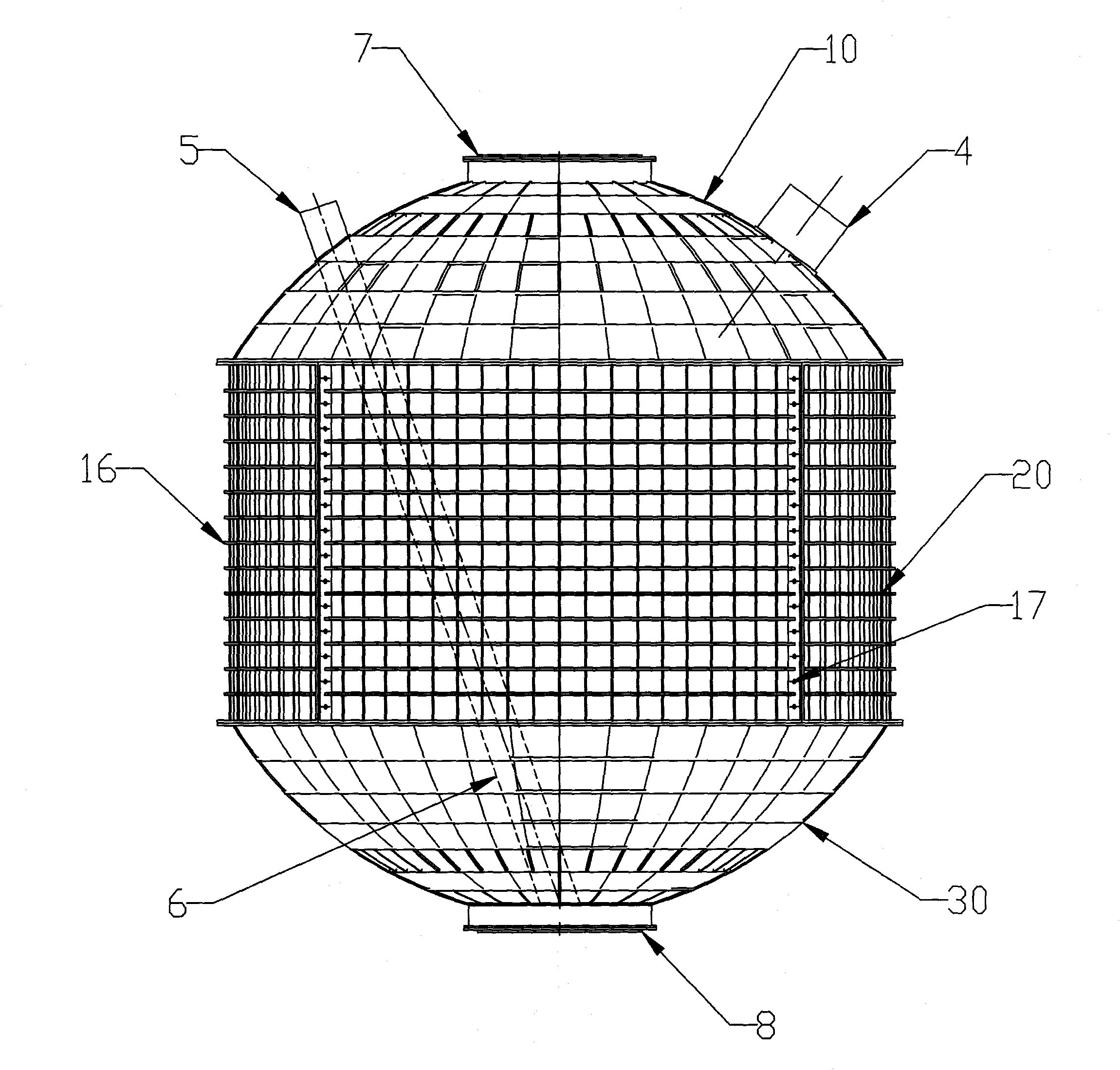
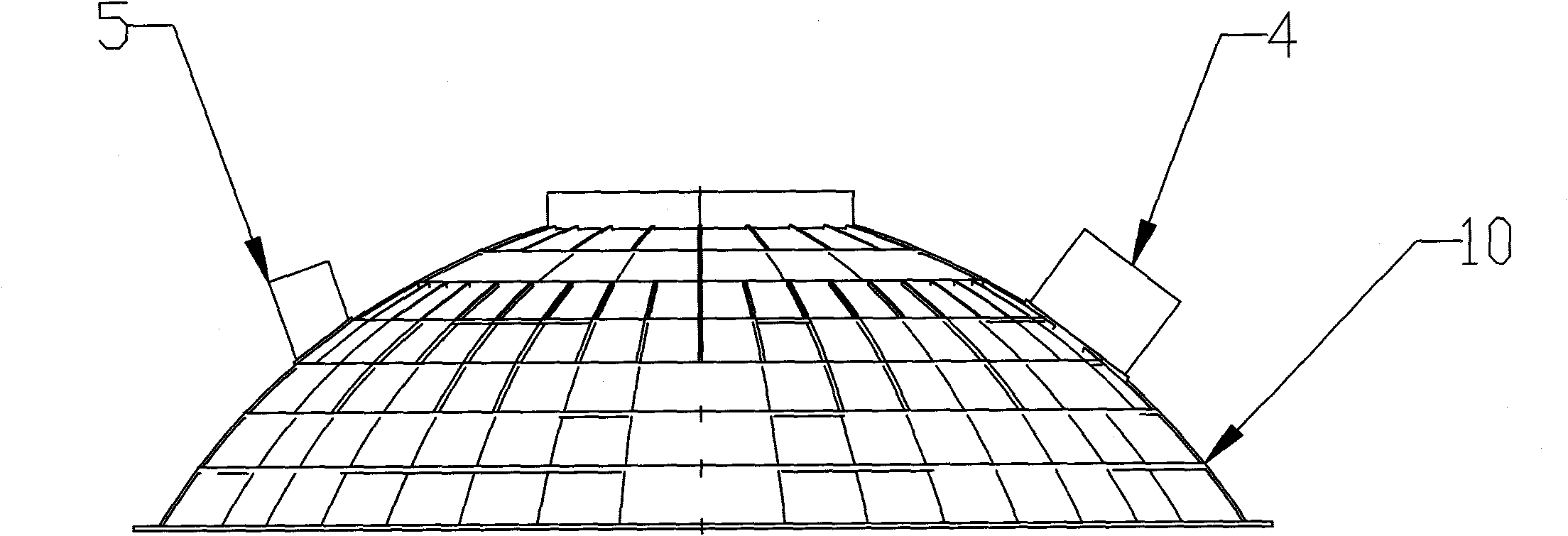
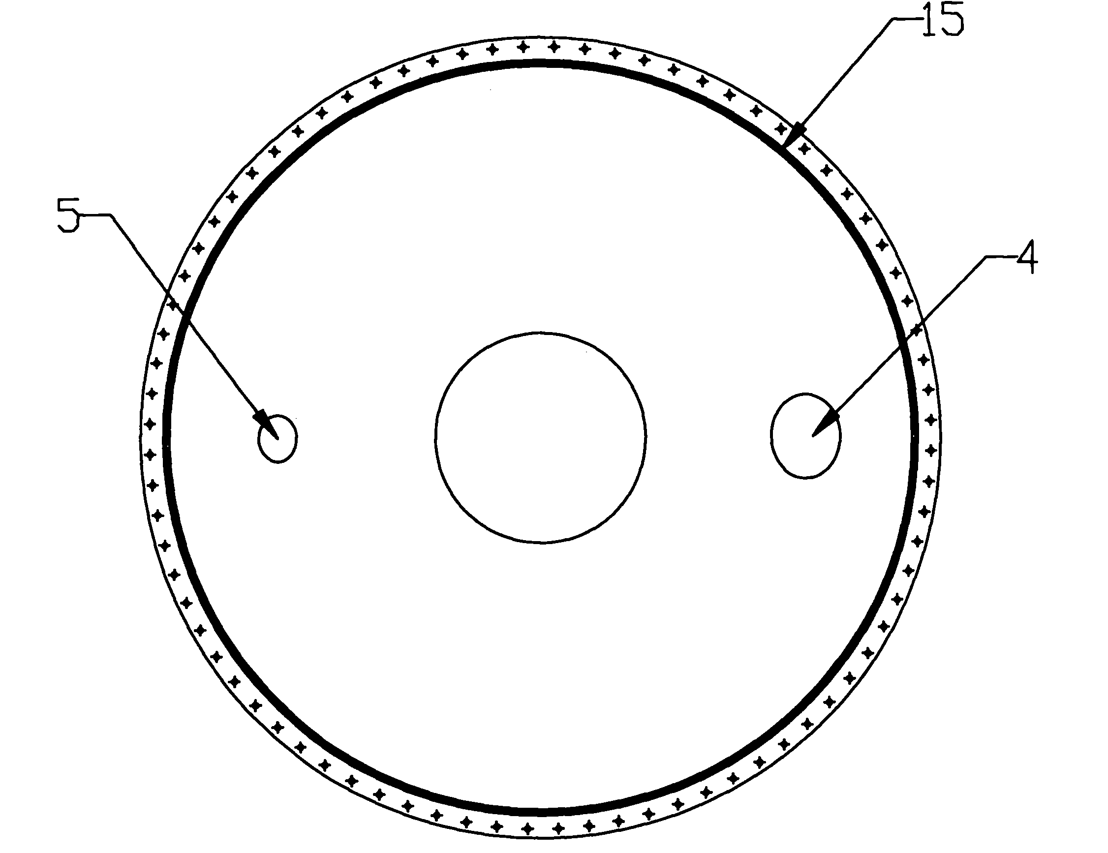
[0032] Such as Figure 1-16 Shown, the cylindrical plastic biogas generator of the present invention comprises the cylindrical container that plastics is made, and described cylindrical container is by hemispherical (the hemispherical shape here is the hemispherical surface along the center of the sphere or the height is less than the radius of the sphere) Spherical crown surface) top 10, cylindrical middle part 20 and hemispherical bottom 30 are sequentially connected to form, and the hemispherical top 10 and bottom 30 are spherical crown surfaces or are formed by splicing at least two fan-shaped tiles respectively, so The fan-shaped tiles are part of the spherical crown; the cylindrical middle part includes at least one section of cylinders, and each section of cylinders is formed by splicing at least two rectangular tiles 2, and the rectang...


PUM


Abstract

The invention discloses a cylindrical plastic methane generator which aims to solve the problems of unadjustable generator volume in the prior art. A hemispheric top part and a hemispheric bottom part are connected with a cylindrical middle part to form a cylindrical container, wherein the hemispheric top part and the hemispheric bottom part consist of spherical crown surfaces or at least two fan-shaped tile petals which are a part of the spherical crown surface; the cylindrical middle part comprises at least one segmental cylinder body, and each segmental cylinder body at least consists of two rectangular tile petals which are a part of a cylindrical surface; the edges of the fan-shaped tile pedals and the rectangular tile petals respectively outwards extend to form outer edges, and a sealing strip is arranged between every two connected outer edges of every two adjacent tile pedals; and every two adjacent outer edges are connected outside the cylindrical container through a plurality of connecting pieces. The section number of combined cylinders is determined according to the scale of the manufactured methane generator, which has great flexibility, reduces the part specification and the mould cost and is economical and applicable. The cylinders are connected outside the cylindrical methane generator, which reduces the corrosion and is convenient to disassemble. The sealing strips improve the tightness and the internal bearing pressure of the methane generator, so that the methane generator is durable and can be used as a cistern for storing water.

Description

technical field [0001] The invention relates to a biogas generator, especially a cylindrical plastic biogas generator. Background technique [0002] Most of the existing plastic biogas generators are spherical or ellipsoidal, and are composed of multiple fan-shaped tiles. Generally, the volume of the biogas generator formed by splicing is fixed, and the existing fan-shaped tiles cannot be spliced ​​according to specific needs. For different biogas generators, the specific specifications of the fan-shaped tiles required for injection molding are different, the required molds will also increase, and the cost is high; and welding or riveting is generally used between two fan-shaped adjacent tiles, and the sealed gas The tightness is poor, the internal pressure of the container is low, the welding process has high requirements for raw materials, and the cost is high, the strength is low, and the hardness is not enough. After the weld is broken, people need to repair the welding ...

Claims


Application Information

Patent Timeline
IPC IPC(8): C12M1/107
CPCY02E50/343C12M23/02C12M23/20C12M21/04Y02E50/30
Inventor 郝松运
Owner 保定广釜塑料制品有限公司
Learn More