
Infrared gas detection system suitable for oil-containing gas analysis of reservoir

A gas detection system and gas analysis technology, which are applied in the direction of analyzing materials, material analysis by optical means, measuring devices, etc., can solve the problems of large operating space, high price, affecting the consistency of spectral data, etc.

Inactive Publication Date: 2010-09-15
中国石油集团川庆钻探工程有限公司长庆录井公司
View PDF5 Cites 24 Cited by
  • Summary
  • Abstract
  • Description
  • Claims
  • Application Information

AI Technical Summary

Problems solved by technology

However, since the temperature has a direct impact on the spectral data of the incoming gas detected by the infrared light through the interferometer and the spectral analysis workstation, the data obtained are different under different temperature conditions, therefore, the temperature will affect the consistency of the spectral data
In addition, the use of infrared light interferometers and spectral analysis workstations is expensive and requires a relatively large operating space

Method used


Image

  • Infrared gas detection system suitable for oil-containing gas analysis of reservoir
  • Infrared gas detection system suitable for oil-containing gas analysis of reservoir
  • Infrared gas detection system suitable for oil-containing gas analysis of reservoir

Examples


Embodiment Construction

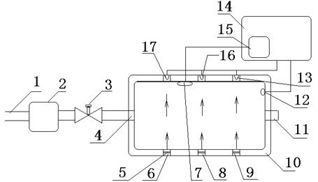
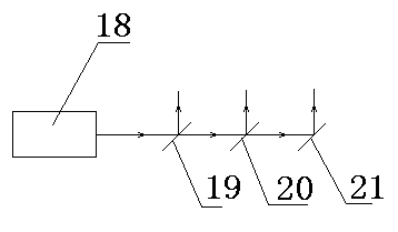
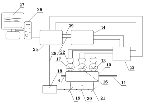
[0023] Such as figure 1 Shown: an infrared gas detection system suitable for oil and gas gas analysis in reservoirs, including a vacuum pump 2 used to send the gas desorbed during the drilling process to a steady flow through the desorbed gas pipeline 1 after dust removal and drying treatment Device 3, after the flow rate is stabilized by the flow stabilization device 3, the gas enters through the detection chamber inlet 4 and is continuously discharged from the detection chamber outlet 11. The detection chamber 10 includes a temperature control mechanism 15 for constant temperature heating of the heating element 7 in the detection chamber 10 Control so that the detection chamber 10 forms a constant temperature gas chamber, and one end of the gas path perpendicular to the constant temperature gas chamber includes light hydrocarbons, heavy hydrocarbons, CO 2 Three beams of infrared light sources at the absorption peak wavelengths of the three gases are light hydrocarbon gas inf...


PUM


Abstract

The invention relates to the technical field of gas detection, in particular to an infrared gas detection system suitable for oil-containing gas analysis of a reservoir, which is characterized by comprising a vacuum pump, wherein the vacuum pump is used for dedusting and drying gas desorbed in a drilling process and conveying the desorbed gas into a constant-current stabilizer through a gas pipeline; after the flow of the gas is stabilized by the constant-current stabilizer, the gas enters from an inlet of a detection chamber and is continuously exhausted from an outlet of the detection chamber; the detection chamber comprises a temperature control mechanism used for thermostatically heating and controlling a heating element in the detection chamber so that the detection chamber forms a constant-temperature gas chamber; three infrared light sources, namely a light hydrocarbon gas infrared light source, a heavy hydrocarbon gas infrared light source and a CO2 infrared light source, which have the absorption peak wavelengths of three gases comprising light hydrocarbon gas, heavy hydrocarbon gas and CO2 gas, are arranged on a gas route vertical to the constant-temperature gas chamber; after passing through the gas vertical to the constant-temperature gas chamber, the three infrared light sources are received by three photoelectric receiving tubes in three photoelectric receiving circuits; and after the three infrared light sources are amplified by an amplification processing circuit, absorption light-wave intensities of the three gases, namely the light hydrocarbon gas, the heavy hydrocarbon gas and the CO2 gas, are displayed on a displayer along a time axis. The system has the characteristics of high reliability, convenient operation and low cost.

Description

technical field [0001] The invention relates to the technical field of gas detection, in particular to an infrared gas detection system suitable for oil and gas gas analysis in reservoirs. The geological information of the set layer. Background technique [0002] How to visually distinguish the dry and wet gas layers in the drilled formation through the gas logging curves on site, and divide the oil, water layers and oil-water contact, so as to provide rapid decision-making services for exploration and development, is an important research goal of gas logging. The gas ratio method has made an effective exploration and attempt for the realization of this goal. This method of interpretation and evaluation is based on the direction and intersection of the three curves of light-medium, light-heavy and heavy-medium hydrocarbon gas ratios to judge and divide the reservoir. The standard combination feature map is used to illustrate, and the feasibility and effectiveness of the me...

Claims


Application Information

Patent Timeline
IPC IPC(8): G01N21/35G01N21/3504
Inventor 郭建友龙利平邵东波戴立斌李永胜郭文斌章志锋王利平周军太邱亮梁立星吴卫东王源刘璐
Owner 中国石油集团川庆钻探工程有限公司长庆录井公司
Learn More