Multistage three-component wave detector device

A geophone, three-component technology, applied in the direction of the seismic signal receiver, etc., can solve the problems such as the inability to accurately analyze the wave field propagation and attenuation laws, the inability of seismic data to fully reflect the geological structure, and the inability to control the direction of the shear wave component geophone, etc. Achieve the effect of reducing survey costs, strong adaptability to small apertures, and improving anti-interference ability

Inactive Publication Date: 2010-09-15
中国石化集团胜利石油管理局地球物理勘探开发公司 +1
View PDF8 Cites 7 Cited by
  • Summary
  • Abstract
  • Description
  • Claims
  • Application Information

AI Technical Summary

Problems solved by technology

With the in-depth research and practice of micro-logging vertical seismic section, this seismic observation method, this type of device still has the following limitations: (1) The main body of the single-stage logging detector determines that it can only be used during use. The main body is collected point by point according to a certain rule, and repeatedly pushes against, repeatedly excites the source, and repeatedly receives signals. The seismic signals received by multiple single-point excitations and single-point receptions cannot well reflect the objective geological conditions of the region; (2) Due to the soft lifting rope structure, the direction of the shear wave component geophone cannot be controlled in the well, and the shear wave component cannot always be ensured. Maintain a specific angle relationship with the source direction
Therefore, the final processed seismic data will not fully reflect the actual geological structure, and it will not be possible to accurately analyze the propagation and attenuation laws of the corresponding wave field.

Method used


Image

  • Multistage three-component wave detector device
  • Multistage three-component wave detector device
  • Multistage three-component wave detector device

Examples


Embodiment Construction

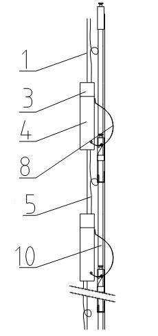
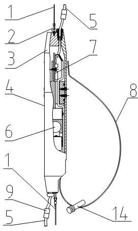
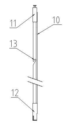
[0015] From figure 1 , figure 2 , image 3 It can be seen from the figure that a multi-stage three-component geophone device of the present invention is provided with several geophone units and push rods 10, each geophone unit is provided with a cylindrical main body 4, and the cylindrical main body 4 is an elongated cylinder Shaped structure, its upper part is connected with end cover 3, and end cover 3 is connected with a ring head bolt 2, and cylindrical main body 4 is connected with steel wire rope 1 through ring head bolt 2. In this way, the geophone units are connected by the steel wire rope 1, and the geophone is lifted and retracted by the steel wire rope 1. The three-component detector core 6 is installed in the cylindrical main body 4 . The core 6 of the three-component geophone is sealed and installed, and is distributed in a Cartesian coordinate system. One of the transverse wave components is consistent with the stretching direction of the elastic support arm...


PUM


Abstract

The invention relates to a multistage three-component wave detector device which is provided with a plurality of wave detector units and a propelling rod; each wave detector unit is provided with a cylindrical main body; a three-component wave detector is installed in the cylindrical main body; the wave detector units are connected by a steel rope; the outer side of the cylindrical main body of the wave detector unit is provided with an elastic support arm; wall attached coupling with a well wall is realized by the elasticity of the elastic support arm; the propelling rod is formed by combining and connecting a plurality of sections of connecting rods; each connecting rod is provided with a fork groove; and the fork groove is matched with a support arm pin shaft which is installed on the elastic support arm for downwards propelling the wave detector units in the fixed direction. The invention has compact structure, convenient and reliable connection and simple and convenient operation and use, has the characteristics of small diameter size, strong small hole diameter adaptability and convenient connection and disassembly, can carry out construction and receiving in the fixed direction, greatly reduces the survey cost, and is suitable for well measuring wave detection of petroleum and earthquake exploration, mine geology, construction engineering, and the like.

Description

technical field [0001] The invention relates to a geophone device for oil exploration, in particular to a multi-stage three-component geophone device suitable for small well diameter and directional detection. Background technique [0002] At present, when we are conducting geological surveys in the petroleum and coal industries, the traditional multi-level three-component detectors are difficult to orientate, or they are large in size, inconvenient to transport, and high in cost; especially for small-caliber surveys During the well operation and the use of multi-stage directional geophones, there are problems such as difficult control of the directionality between each geophone, poor coupling performance between the geophone and the well wall, and the large size of the geophone; especially when When there is mud under the well, it is difficult for ordinary three-component geophones to be pushed to the predetermined detection position. There are large-scale well logging equ...

Claims


Application Information

Patent Timeline
Patent Type & Authority Applications(China)
IPC IPC(8): G01V1/18
Inventor 胡立新颜永安刘志田宋加恩尚应军孙中心吴学兵申恒广杨怀春田殿仓安峰王甲甲
Owner 中国石化集团胜利石油管理局地球物理勘探开发公司
Why Eureka
Try Eureka