Gas feeding device, treating device, treating method, and storage medium

一种气体供给、气体的技术,应用在薄料处理、电气元件、运输和包装等方向,能够解决没有记载气体解决方法等问题,达到自由度大、容易制造、生产率提高的效果

Inactive Publication Date: 2010-09-22
TOKYO ELECTRON LTD
View PDF1 Cites 13 Cited by
  • Summary
  • Abstract
  • Description
  • Claims
  • Application Information

AI Technical Summary

Problems solved by technology

However, in Japanese Patent Laid-Open No. 7-22323, there is no description of a solution to the above-mentioned problems that occur when gases are replaced with each other.

Method used


Image

  • Gas feeding device, treating device, treating method, and storage medium
  • Gas feeding device, treating device, treating method, and storage medium
  • Gas feeding device, treating device, treating method, and storage medium

Examples


no. 1 approach

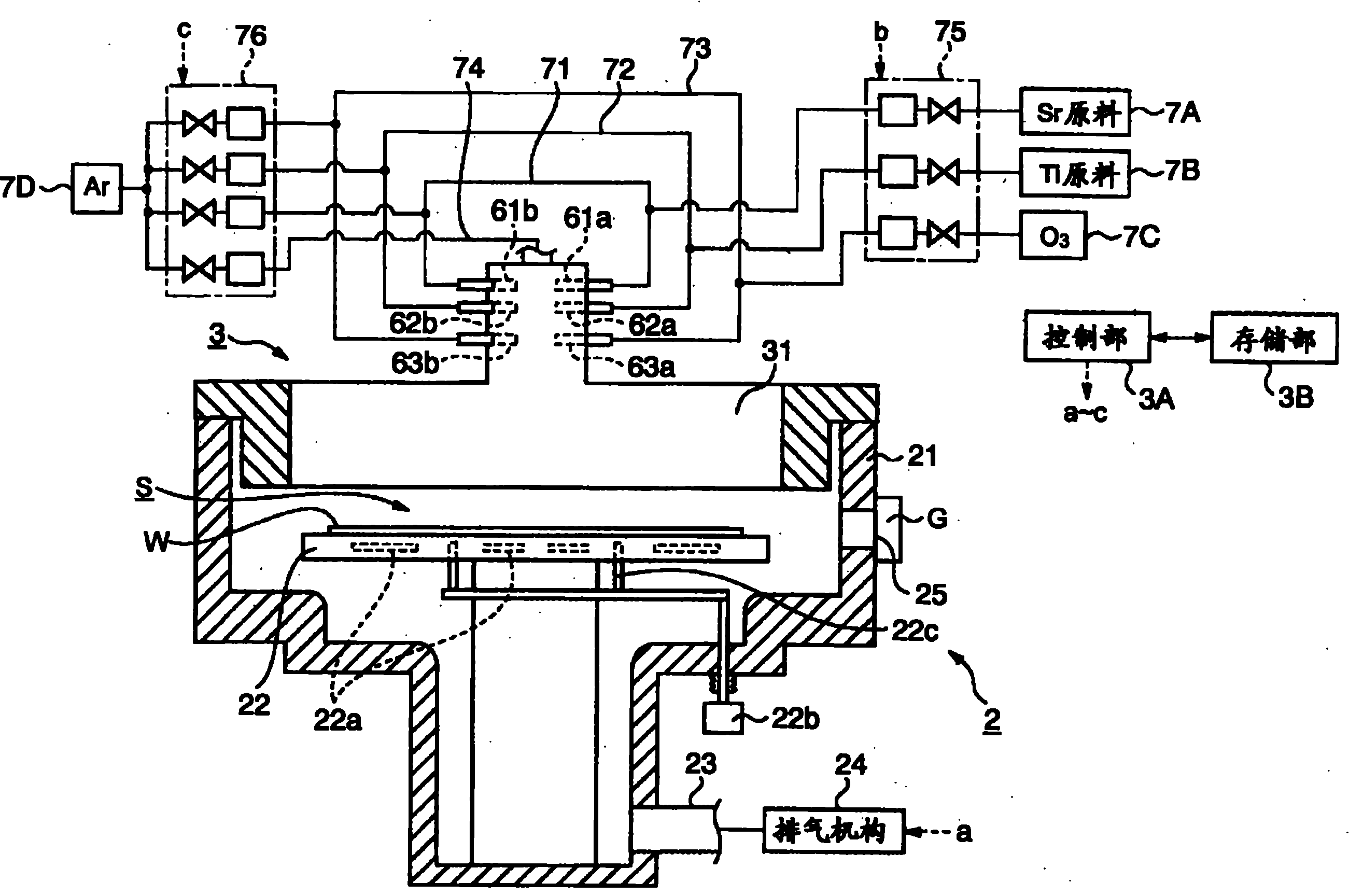
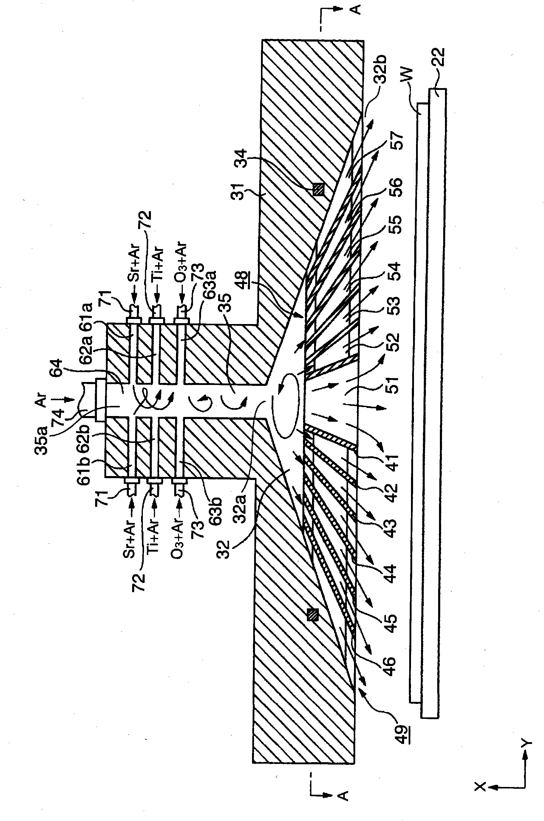
[0053] First, edge reference figure 1 , the overall configuration of the film forming apparatus 2 as an embodiment of the present invention will be described.

[0054] The film forming apparatus 2 of the present embodiment has a function of using, for example, a source gas containing strontium (Sr) (hereinafter referred to as Sr source gas) as the first process gas, and a source gas containing titanium (Ti) (hereinafter referred to as referred to as Ti raw material gas) as the second processing gas, and make these gases and ozone (O 3 ) gas reaction, using the ALD process to form strontium titanate (SrTiO 3 , hereinafter abbreviated as STO) film.

[0055] The film forming apparatus 2 includes a processing container 21 . In the processing container 21, a mounting table 22 for horizontally mounting the wafer W is provided. Inside the mounting table 22, a heater 22a constituting a temperature adjustment mechanism for the wafer W is provided. In addition, three lift pins 22c...

no. 2 approach

[0093] Next, in reference to Figure 11 Along with (a), a second embodiment of the gas supply device constituting the gas supply unit of the above-mentioned film forming apparatus 2 will be described.

[0094] Although Figure 11 The gas supply unit 100 shown in (a) has the same configuration as the gas supply unit 3, however, the above-mentioned dividing members 41 to 46 are not provided in the gas circulation space 32, and instead of them, the gas circulation space 32 is divided in the circumferential direction. Plate-shaped partition members 103-106 arranged in a manner. Each of the partition members 103 to 106 extends radially from the center of the gas circulation space 32 toward the inner peripheral surface 33 of the main body portion 31 .

[0095] For example, one end of each partition member 103-106 is supported by the said inner peripheral surface 33, and the other end is supported by the support member 107 provided in the center of the said radial direction. Figu...

no. 3 approach

[0101] Next, a third embodiment of the gas supply device constituting the gas supply unit of the above-described film forming apparatus 2 will be described. In referring to the sectional perspective view as this embodiment Figure 12 At the same time, the description will focus on the differences from the gas supply unit 3 .

[0102] Figure 12 The main body part 120 of the gas supply part 110 shown has a flat circular shape. Moreover, in the main body part 120, instead of the gas circulation space 32 whose diameter was enlarged in the lower side, the disk-shaped gas circulation space 121 is formed. In addition, the partition members 41 to 46 are not provided in the gas circulation space 121 , and the plate-shaped member 111 is provided on the downstream end 121 a side of the gas circulation space 121 .

[0103] Annular slits 112 divided into four in the circumferential direction are concentrically formed in the plate-shaped member 111 . Figure 13 (a) is a bottom view of ...


PUM

PropertyMeasurementUnit
diameteraaaaaaaaaa

Abstract

Provided is a gas feeding device (3) comprising a body portion (31) forming a substantially conical gas passage space (32) for passing gases from the side of a radially reduced end (32a) to the side of a radially enlarged end (32b), gas introduction ports (61a to 63a, 61b to 63b and 64) formed in the gas passage space (32) on the side of the radially reduced end (32a), for introducing the gases into the gas passage space (32), and a plurality of partition members (41 to 46) disposed in the gas passage space (32) and defining the gas passage space (32) concentrically. The diverging degree of one of the partition members (42 to 46) is larger than the diverging degree of that of the partition members (41 to 45), which is adjacent, on the radially inner side, to the former. As a result, the conductance in the gas passage inside of the gas feeding device can be made larger than that of the gas shower head of the prior art, thereby improving the replaceability of the gases in the gas passage.

Description

technical field [0001] The present invention relates to a gas supply device for supplying a processing gas to a substrate, a processing device including the gas supply device, a processing method using the gas supply device, and a storage medium. Background technique [0002] Currently, a gas shower head is used as a gas supply device for a device that performs CVD (chemical vapor deposition), etching, and the like. This gas shower head is made into a flat cylindrical shape, diffuses the gas supplied from the gas inlet provided on the upper part in the internal diffusion space, and supplies it in a shower form from a plurality of holes formed on the lower surface. As a gas shower head that supplies multiple types of processing gases, there are so-called pre-mixing type gas shower heads in which multiple types of processing gases are mixed and supplied in the middle of the gas flow path of one system, and gas shower heads that separately set gas for multiple types of gases. ...

Claims


Application Information

Patent Timeline
Patent Type & Authority Applications(China)
IPC IPC(8): H01L21/31C23C16/455H01L21/205H01L21/3065
CPCC23C16/45565C23C16/45531H01L21/0228H01L21/02197C23C16/45582C23C16/45591C23C16/409Y10T137/4673H01L21/0262H01L21/3065
Inventor 津田荣之辅
Owner TOKYO ELECTRON LTD
Why Eureka
Try Eureka