Automatic steel ball casting forming machine

A molding machine and steel ball technology, applied in the direction of casting molding equipment, molding machines, casting molds, etc., can solve the problems of not being able to meet mass production, high labor intensity of workers, poor production efficiency, etc., to meet the requirements of mass production, structure Compactness and the effect of improving yield

Inactive Publication Date: 2010-09-29
NANJING COLLEGE OF CHEM TECH
View PDF5 Cites 27 Cited by
  • Summary
  • Abstract
  • Description
  • Claims
  • Application Information

AI Technical Summary

Problems solved by technology

[0002] The production of steel balls is produced by iron molds. The molten iron is formed in the cavity of the iron mold. Before forming, the iron mold is protected, and a layer of molding sand is covered at the gate of the iron mold. In the current steel ball production enterprises, this pr

Method used


Image

  • Automatic steel ball casting forming machine
  • Automatic steel ball casting forming machine
  • Automatic steel ball casting forming machine

Examples


Embodiment Construction

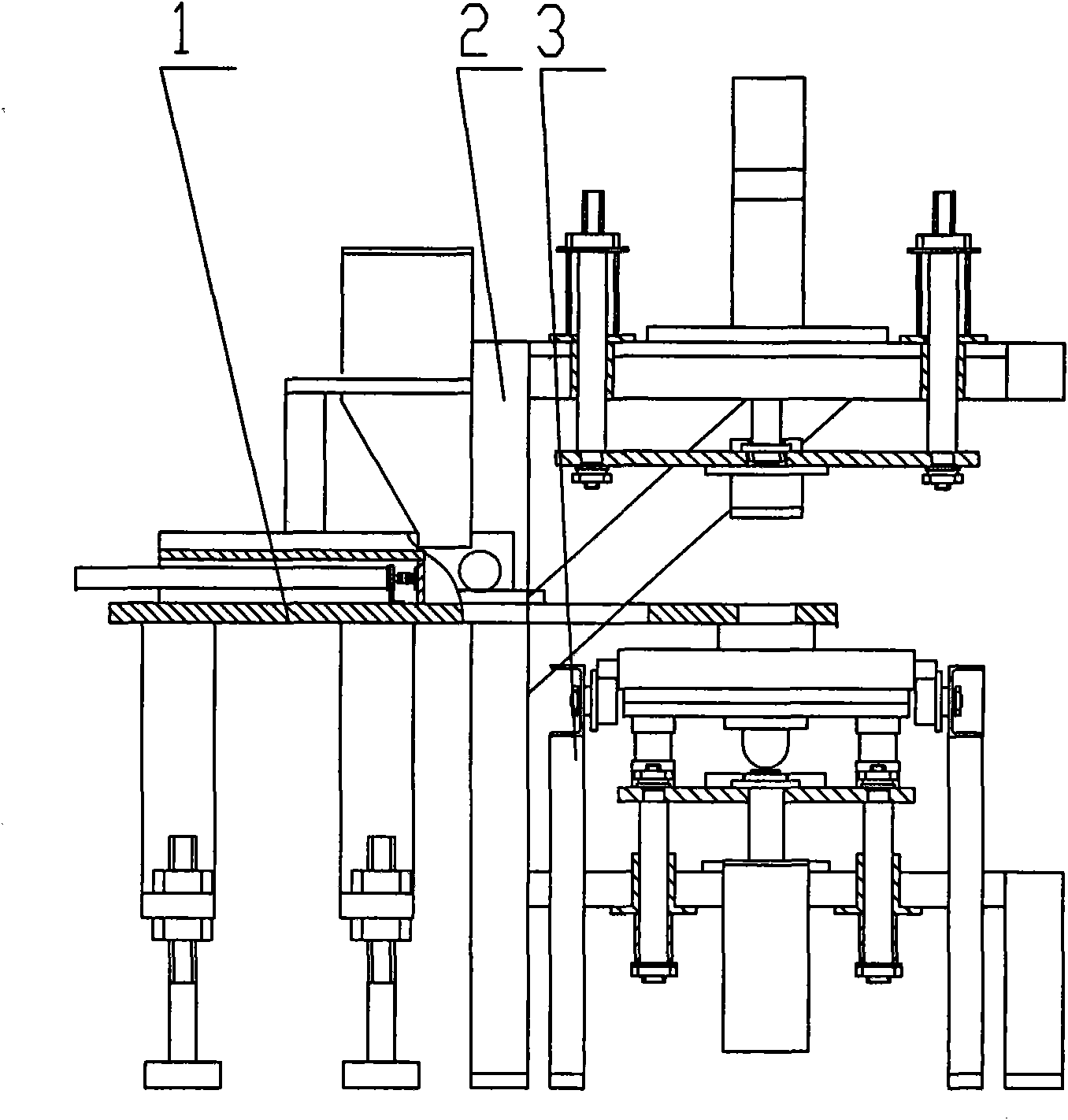
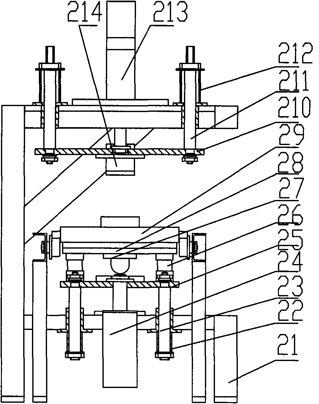
[0018] like figure 1 The automatic steel ball machine shown is composed of a feeder 1, a molding machine 2, and a guide rail 3. The feeder 1 is located at the rear of the molding machine 2, and the mold template 29 is located on the vibration table of the molding machine 2. When forming, the steel ball mold is located on the mold plate 29, and the round mouth of the feeding box bottom plate 13 of the feeder 1 is aligned with the mold plate. When working, the feeder 1 sends the molding sand to the cavity of the mold, and the vibrating table The vibration drives the mold to vibrate, the pressure head 214 presses down to form, and the molding sand is formed in the mold.

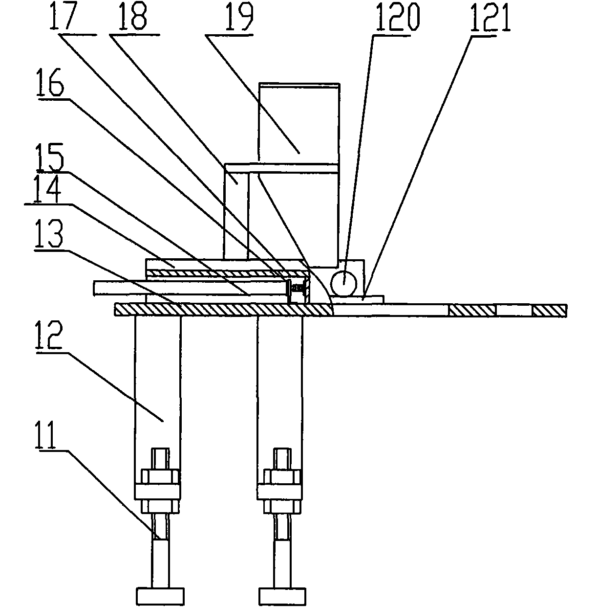
[0019] like figure 2 The shown feeder 1 is mounted on the rear of the molding machine 2, and consists of height adjustment bolts 11, adjustment feet 12, feed box bottom plate 13, feed box 14, telescopic cylinder 15, fixed bracket 16, material partition plate 17, hopper frame 18 , Storage box 19, guide wheel 1...


PUM


Abstract

The invention discloses an automatic steel ball casting forming machine, and relates to a steel ball casting production technique, in particular to the technique for producing a casting head in steel ball casting production. The automatic steel ball casting forming machine mainly comprises three parts, namely a feeder, a forming main machine and a guide rail, wherein the feeder is positioned at the back of the forming main machine; and the guide rail is vertical to the feeder. The automatic steel ball casting forming machine has compact and rational structure; the up-and-down movement of the feeder and a pressure head and the up-and-down movement of a mould template are finished by hydraulic or pneumatic drive; and the implementation of each movement is controlled by a programmable logic controller (PLC) of an electrical system so as to realize automation of the whole process; and the automatic steel ball casting forming machine greatly reduces the labor intensity in the steel ball casting production, improves the work efficiency, improves the product qualification rate, and meets the requirement of mass production to the hilt.

Description

technical field [0001] The invention relates to the casting production technology of steel balls, in particular to the production technology of the pouring riser in the steel ball casting production. Background technique [0002] The production of steel balls is produced by iron molds. The molten iron is formed in the cavity of the iron mold. Before forming, the iron mold is protected, and a layer of molding sand is covered at the gate of the iron mold. In the current steel ball production enterprises, this process It is done manually by manually covering the sprue gate of the iron mold with molding sand, compacting it manually, and digging the sprue gate manually. The production efficiency is poor, the labor intensity of the workers is high, and it cannot meet the needs of mass production. Contents of the invention [0003] The purpose of the present invention is to design a kind of automatic steel ball casting molding machine which can improve the low efficiency and high...

Claims


Application Information

Patent Timeline
IPC IPC(8): B22C15/14B22C9/22B22C9/08
Inventor 仲崇生潘传九靳兆文杨英发徐永军
Owner NANJING COLLEGE OF CHEM TECH
Why Eureka
Try Eureka