Steam supply system for steam air heater of utility boiler

A technology of steam supply system and power station boiler, applied in steam boilers, steam boiler accessories, steam boiler components, etc., can solve the problems of high operating cost, unrecovered working medium, and high quality of steam supply for air heaters. The effect of improving the heat recovery efficiency and reducing the operating cost of power generation

Inactive Publication Date: 2011-07-27
魏熙臣
View PDF3 Cites 0 Cited by
  • Summary
  • Abstract
  • Description
  • Claims
  • Application Information

AI Technical Summary

Problems solved by technology

[0006] The purpose of the present invention is to solve the problems of unutilized exhaust steam heat of deaerator, unrecovered working medium, high operating cost, high quality of steam supplied by air heater and low heat recovery efficiency of steam turbine generator set, and further provide a Power station boiler heater steam supply system

Method used


Image

  • Steam supply system for steam air heater of utility boiler
  • Steam supply system for steam air heater of utility boiler
  • Steam supply system for steam air heater of utility boiler

Examples


specific Embodiment approach 1

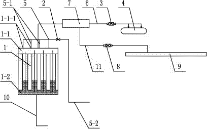
[0010] Specific implementation mode one: combine figure 1 Describe this embodiment, a steam supply system for a utility boiler heater in this embodiment includes a heater 1, a deaerator exhaust valve 3, a deaerator 4, a steam supply pipe 6 and a drain pipe 10, the heater The steam inlet header 1-1 of the fan 1 communicates with the deaerator 4 through the steam supply pipe 6, and the deaerator exhaust valve 3 is installed on the steam supply pipe 6, and the drain header of the air heater 1 Drain pipe 10 is installed on 1-2.

[0011] The air heater 1 is a finned air heater, a finned air heater or a bare tube air heater, which is the prior art. This embodiment is especially suitable for the case where the maximum pressure of the deaerator is lower than the design pressure of the air heater.

specific Embodiment approach 2

[0012] Specific implementation mode two: combination figure 1 This embodiment will be described. The deaerator exhaust valve 3 in this embodiment is a deaerator exhaust regulating valve. Such setting can effectively prevent the air heater 1 from overpressure. Other compositions and connections are the same as in the first embodiment.

specific Embodiment approach 3

[0013] Specific implementation mode three: combination figure 1 To illustrate this embodiment, the steam supply system of this embodiment is also added with an exhaust valve 2 and an exhaust pipe 5, and a plurality of exhaust holes are opened on the upper end surface of the steam inlet header 1-1 of the air heater 1 1-1-1, the exhaust pipe 5 is composed of an exhaust main pipe 5-2 and a plurality of exhaust branch pipes 5-1, and one end of each exhaust branch pipe 5-1 is connected with the corresponding exhaust hole 1-1 -1 communicates, and the other end of each exhaust branch pipe 5-1 communicates with the exhaust main pipe 5-2, and the exhaust valve 2 is installed on the exhaust main pipe 5-2. With such arrangement, the air accumulated in the steam inlet header 1-1 will be discharged in time to prevent the heat exchange from being affected. Other compositions and connections are the same as those in Embodiment 1 or Embodiment 2.


PUM


Abstract

The invention discloses a steam supply system for a steam air heater of a utility boiler, which relates to a steam supply system for a steam air heater. The invention solves the problems that: the exhausted steam heat of the deaerator is not utilized, the working medium is not recovered, the operation cost is high, the quality of the steam supplied by the steam air heater is too high, and the heat-recovering efficiency of the steam turbine generator unit is low. The steam supply system comprises the steam air heater, a deaerator stream-exhausting valve, a deaerator, a steam supply tube and a draining tube, a steam intake header of the steam air heater is communicated with the deaerator through the steam supply tube, the deaerator steam-exhausting valve is mounted on the steam supply tube,and a draining header of the steam air heater is provided with the draining tube. The invention can ensure that the heat of the steam exhausted by the deaerator can be sufficiently utilized and that all of the working medium can be recovered; the quality of the steam supplied by the steam air heater is decreased; the temperature-reducing water for the steam supplied by the steam air heater is dispensed with, energy can be utilized according to quality, and the heat-recovering efficiency of the steam turbine generator unit is increased. The invention also reduces the operation cost of electricity generation. The invention is applicable to utility boilers.

Description

technical field [0001] The invention relates to a steam supply system for an air heater, in particular to a steam supply system for an air heater of a power station boiler, and belongs to the field of thermal power engineering of a power station. Background technique [0002] In thermal power plants in areas with low-temperature seasons, in order to prevent low-temperature corrosion at the bottom of the boiler due to heating, most of the boiler supply fans and primary fans are equipped with heaters. The heat source of the heaters comes from the factory steam system. Arrange the drain tank at the low position, the drain will flow to the drain tank by gravity, and then be pumped to the deaerator by the drain pump. Factory steam generally has a superheat of about 100°C. Since the heat release coefficient of superheated steam is 50-100 times smaller than that of steam condensation, in order to improve the heat exchange capacity of the air heater, it is generally necessary to use...

Claims


Application Information

Patent Timeline
Patent Type & Authority Patents(China)
IPC IPC(8): F23L15/00F22B37/00
CPCY02E20/34Y02P80/15
Inventor 魏熙臣魏来
Owner 魏熙臣
Why Eureka
Try Eureka