Continuous waste plastics refining unit

A technology for oil refining equipment and waste plastics, which is used in the petroleum industry and the preparation of liquid hydrocarbon mixtures. The effect of operational safety

Inactive Publication Date: 2010-10-06
曹骏
View PDF5 Cites 8 Cited by
  • Summary
  • Abstract
  • Description
  • Claims
  • Application Information

AI Technical Summary

Problems solved by technology

[0002] At present, all waste plastic refining equipment in the world is intermittent rather than continuous. There are five major defects in the process of waste plastic refining: 1. It cannot continuously react and discharge slag, and can only burn one pot and rest one pot; 2. There is no Effective dechlorinatio

Method used


Image

  • Continuous waste plastics refining unit
  • Continuous waste plastics refining unit

Examples


Embodiment Construction

[0008] A preferred embodiment will be given below, and the present invention will be described more clearly and completely in conjunction with the accompanying drawings.

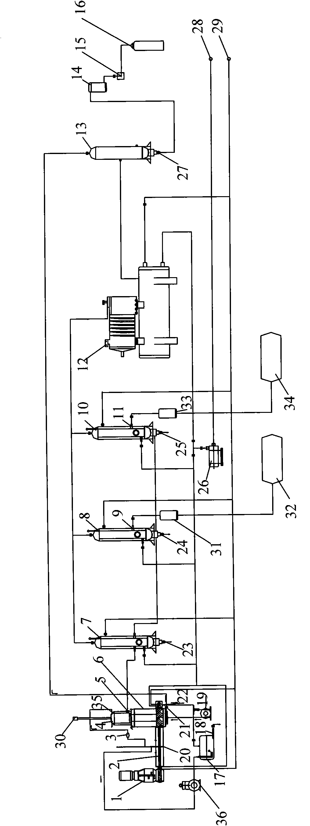
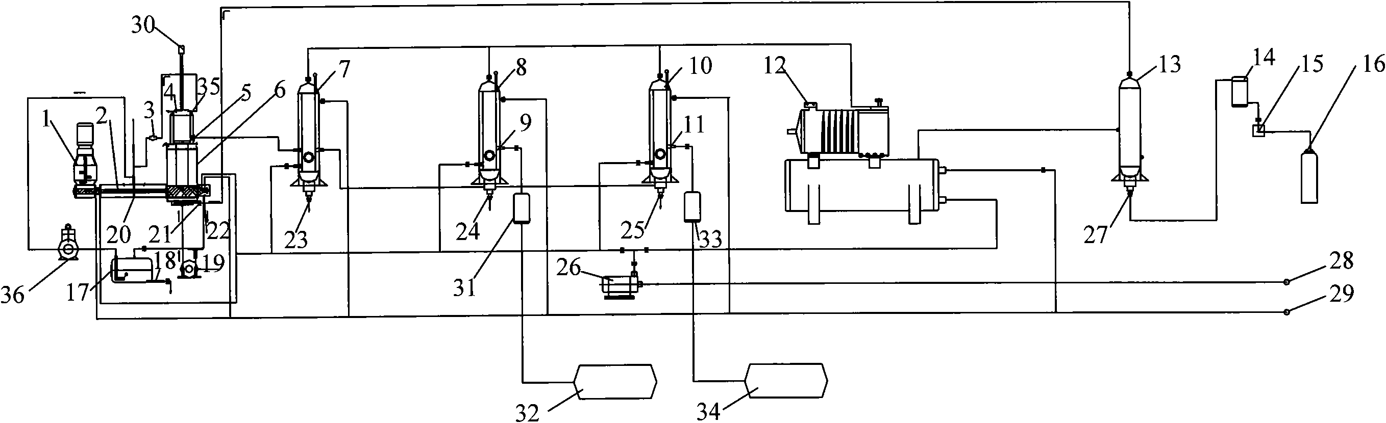
[0009] Such as figure 1 As shown, the continuous type waste plastic refining device of the present invention includes a feeder 1, a feeding screw propeller 2, a safety valve 3, a catalytic tank 4, an oil and gas outlet 5, a cracker 6, an intermediate condenser 7, and a gasoline distillation tank 8 , gasoline outlet 9, diesel rectification tank 10, diesel oil outlet 11, compressor 12, first gas storage tank 13, first filter 14, air release valve 15, second gas storage tank 16, bubbling chamber 17, hydrochloric acid Discharge port 18, fan 19, dechlorinator 20, burner air inlet 21, slag discharge port 22, first water discharge port 23, second water discharge port 24, heavy oil discharge port 25, water pump 26, liquefied gas outlet 27, cooling Water inlet 28, cooling water outlet 29, exhaust pipe 30, second fil...


PUM


Abstract

The invention discloses a continuous waste plastics refining unit, comprising elements such as a feeder and the like. The feeder is connected with a feed worm propeller; an oil gas outlet is arranged below a catalytic tank and is connected with an intercondenser; a hydrochloric acid discharge outlet is arranged on a bubbling chamber; the feed worm propeller is inserted into a dechlorination device; a bleed hole is positioned on the top end of a cracker; a fan is arranged below the cracker; the gas inlet of a burner is positioned below the cracker and is connected with a first gas storage tank; a first dewatering outlet is positioned below the intercondenser; a heavy oil discharge port is positioned below a diesel rectification tank; a liquefied gas outlet is positioned below the first gasstorage tank; a cooling water inlet is connected with a gasoline rectification tank, the diesel rectification tank, a compressor condenser, a deslagging device and a feeding device via water pumps; asecond filter is connected with a gasoline storage tank; a third filter is connected with a diesel storage tank; and a vacuum pump is positioned between the bubbling chamber and the dechlorination device. The invention can react, crack, reduce, catalyze and refine continuously.

Description

technical field [0001] The invention relates to a waste plastic refining device, in particular to a continuous waste plastic refining device. Background technique [0002] At present, all waste plastic refining equipment in the world is intermittent rather than continuous, and there are five major defects in the process of waste plastic refining: 1. It cannot continuously react and discharge slag, and can only burn one pot and rest one pot; 2. There is no Effective dechlorination device is easy to generate waste gas; 3. In the process of cracking and catalysis, carbon deposits are generated, which is easy to block the passage; 4. It cannot be continuously compressed to make non-condensable gas into a liquid state; 5. The distillation method is simple, and the output oil is mixed , The oil quality is poor. Contents of the invention [0003] The technical problem to be solved by the present invention is to provide a continuous waste plastic refining device capable of contin...

Claims


Application Information

Patent Timeline
IPC IPC(8): C10G1/10
Inventor 曹关权曹骏
Owner 曹骏
Why Eureka
Try Eureka