Electric roller brush

A rolling brush, electric technology, applied in the direction of construction, building structure, etc., can solve the problems of easy-to-pollute decorative ornaments, low work efficiency, dripping and other problems, and achieve the effect of wide application range, high work efficiency, and simple filling.

Inactive Publication Date: 2010-10-06
宁波松园机电科技有限公司
View PDF6 Cites 8 Cited by
  • Summary
  • Abstract
  • Description
  • Claims
  • Application Information

AI Technical Summary

Problems solved by technology

[0002] The roller brush is a practical painting tool. There are three main structures of the roller brush commonly used in the market: the first is the ordinary roller brush, which needs to be used to stick the paint while rolling the wall. This structure has low working efficiency. The dripping of the paint is serious, especially when the ceiling is painted, and the dripping of the paint will also cause damage to the human skin, and pollute the clothes and the floor; High-pressure spraying, the high-speed mist paint sprayed by the roller brush is easy to pollute other indoor decorations, and what is more serious is that this mist paint is inhaled by people, causing harm to people's physical and mental health; the third structure Similar to the "portable electric roller brush machine" with the published Chinese patent No. 00219874.6, it is mainly composed of a material barrel, a motor, a main engine pump, a feeding pipe, a roller brush, etc. A manual switch is installed on the barrel. Although this tool overcomes the disadvantages of the first two tools, there are still many defects in the actual use process. First, this rolling brush is

Method used


Image

  • Electric roller brush
  • Electric roller brush
  • Electric roller brush

Examples


Embodiment Construction

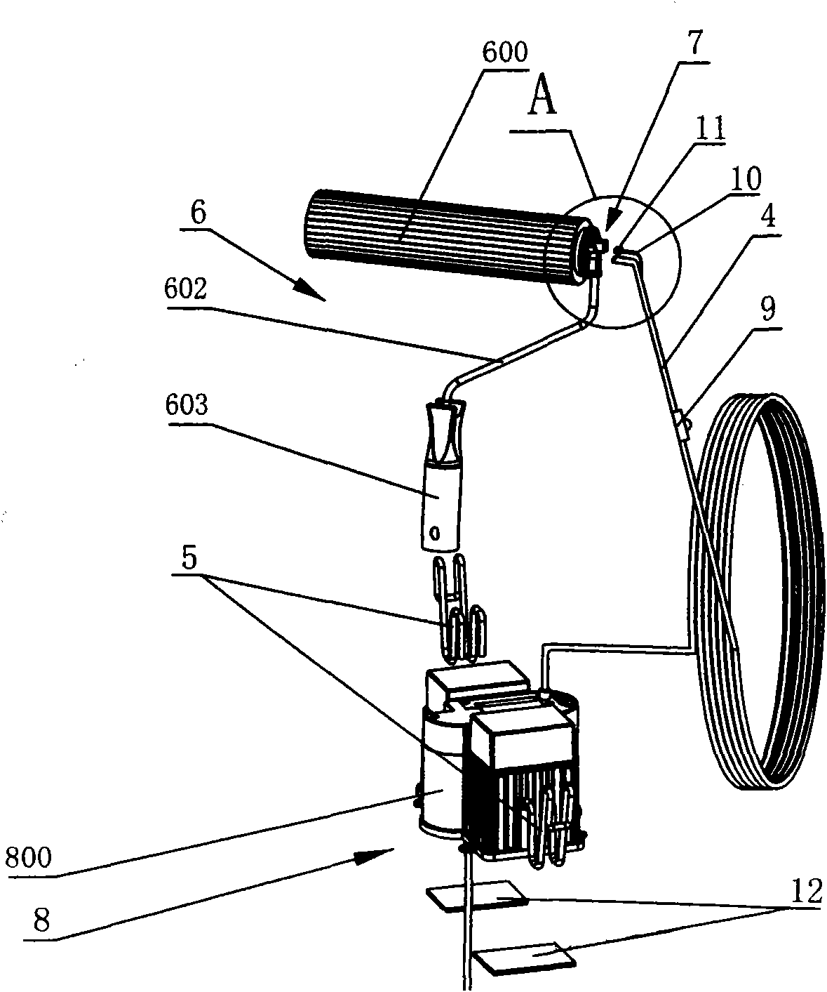
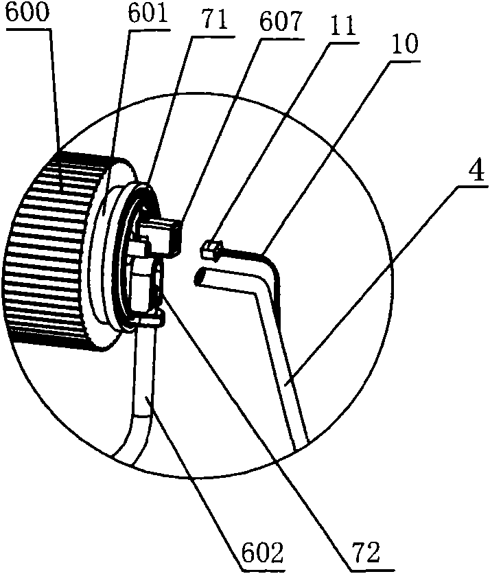
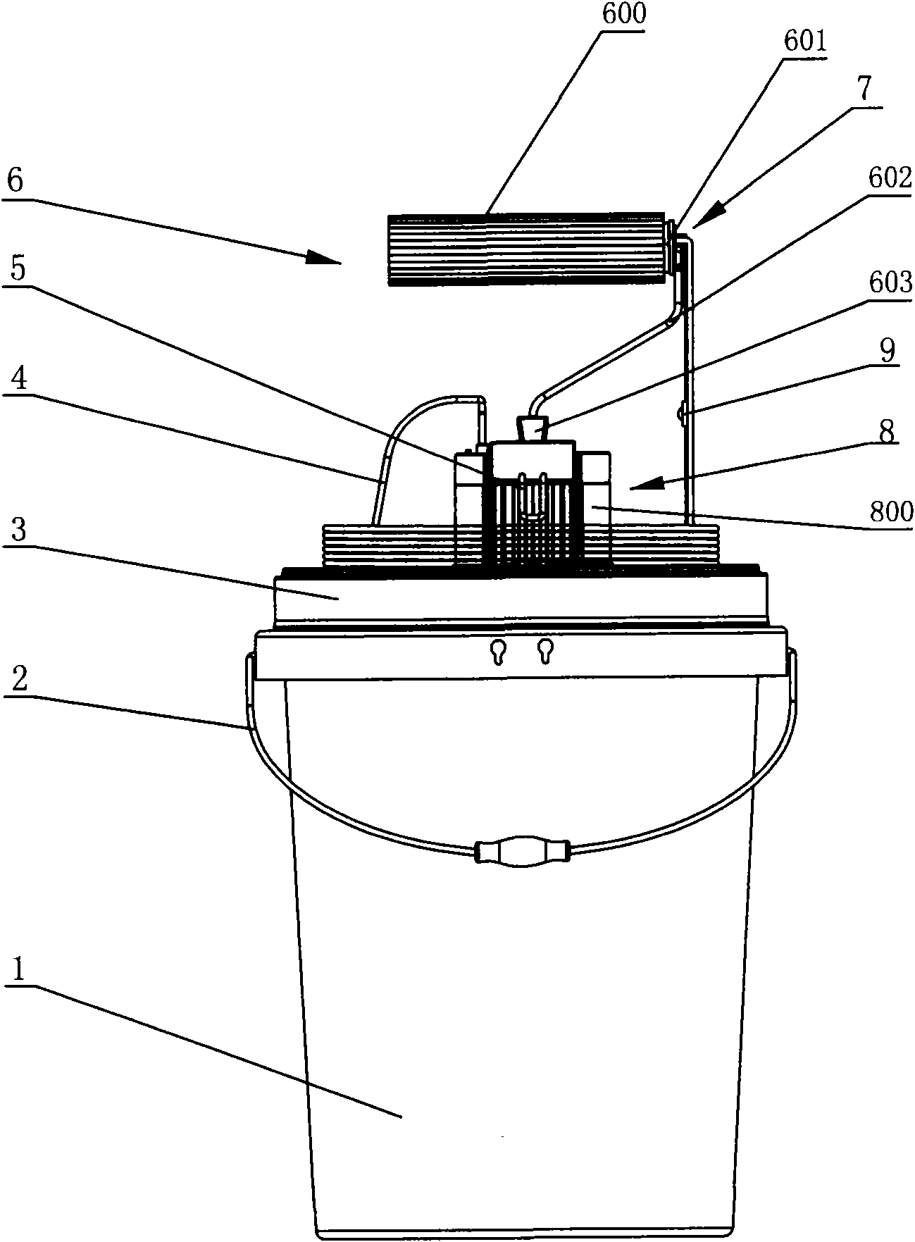
[0035] The embodiments of the present invention will be described in detail below according to the above-mentioned drawings. like Figure 1 ~ Figure 2 As shown in 0, 1. material barrel, 2. lifting ring, 3. barrel cover, 4. feeding pipe, 5. bracket, 6. roller brush, 600. bristle, 601. right roller sleeve, 602. brush rod, 603. Brush handle, 604. Bolt, 605. Limiting ring, 606. Left roller sleeve, 607. Connecting socket, 608. Rib, 609. Filter cover, 610. Drum, 611. Inner ring gear, 612. Left Fixed ring, 613. Discharge pipe, 614. Discharge hole, 615. Support rod, 616. Right fixed ring, 617. Connector, 618. Belt, 619. Gear frame, 7. Switch device, 71. Roller jacket, 72. Groove, 73. Cam, 74. First stage gear, 75. Third stage gear, 76. Second stage gear, 77. Micro switch, 78. Concave edge, 79. Convex edge, 8. Host pump . Wheel slot, 810. Runner, 811. Runner shaft, 812. Pressure tube wheel, 813. Gap, 9. Manual switch, 10. Wire, 11. Plug, 12. Adhesive, 13. Motor, 14. Battery, 15. Ba...


PUM


Abstract

The invention discloses an electric roller brush, which is a coating tool mainly for roll coating on a wall surface and mainly comprises a motor, a main machine pump, a feeding pipe, a storage battery, a roller brush and other structures. The electric roller brush is arranged on a material barrel with a barrel lid; the lower end of the feeding pipe passes through the main machine pump and extends into the material barrel to be in contact with coating; the upper end of the feeding pipe is connected with the roller brush; and the coating at the lower end of the feeding pipe is continuously delivered to the roller brush at the upper end of the feeding pipe by using the motor to start the main machine pump to work. The technical scheme disclosed by the invention comprises the point that a switch device with a more novel structure is arranged on the roller brush and is synchronously started by rotating a manually-driven roller, thereby realizing the quantitative feeding of the roller brush and avoiding the defects of serious leakage, the pollution to peripheral environment and the damage to human body of the traditional structure due to a lagged feeding mode. The improved structure has the advantages of small volume, simple and convenient filler, high quantity, simple maintenance, light roll coating, convenience, high working efficiency, wide application range and the like.

Description

technical field [0001] The invention relates to a rolling brush structure for rolling coating walls, in particular to an electric rolling brush. Background technique [0002] The roller brush is a practical painting tool. There are three main structures of the roller brush commonly used in the market: the first is the ordinary roller brush, which needs to be used to stick the paint while rolling the wall. This structure has low working efficiency. The dripping of the paint is serious, especially when the ceiling is painted, and the dripping of the paint will also cause damage to the human skin, and pollute the clothes and the floor; High-pressure spraying, the high-speed mist paint sprayed by the roller brush is easy to pollute other indoor decorations, and what is more serious is that this mist paint is inhaled by people, causing harm to people's physical and mental health; the third structure Similar to the "portable electric roller brush machine" with the published Chine...

Claims


Application Information

Patent Timeline
IPC IPC(8): E04F21/08
Inventor 黄权
Owner 宁波松园机电科技有限公司
Why Eureka
Try Eureka