
Illumination system

A technology of lighting system and light-transmitting part, which is applied in the field of lighting system, can solve the problem that the light distribution curve of the light source cannot be adjusted, etc., and achieve the effect of simple structure and high flexibility

Inactive Publication Date: 2010-10-06
JIANGSU ZHONGKE GLOBALTEK OPTOELECTRONICS LIGHT ENERGY
View PDF0 Cites 2 Cited by
  • Summary
  • Abstract
  • Description
  • Claims
  • Application Information

AI Technical Summary

Problems solved by technology

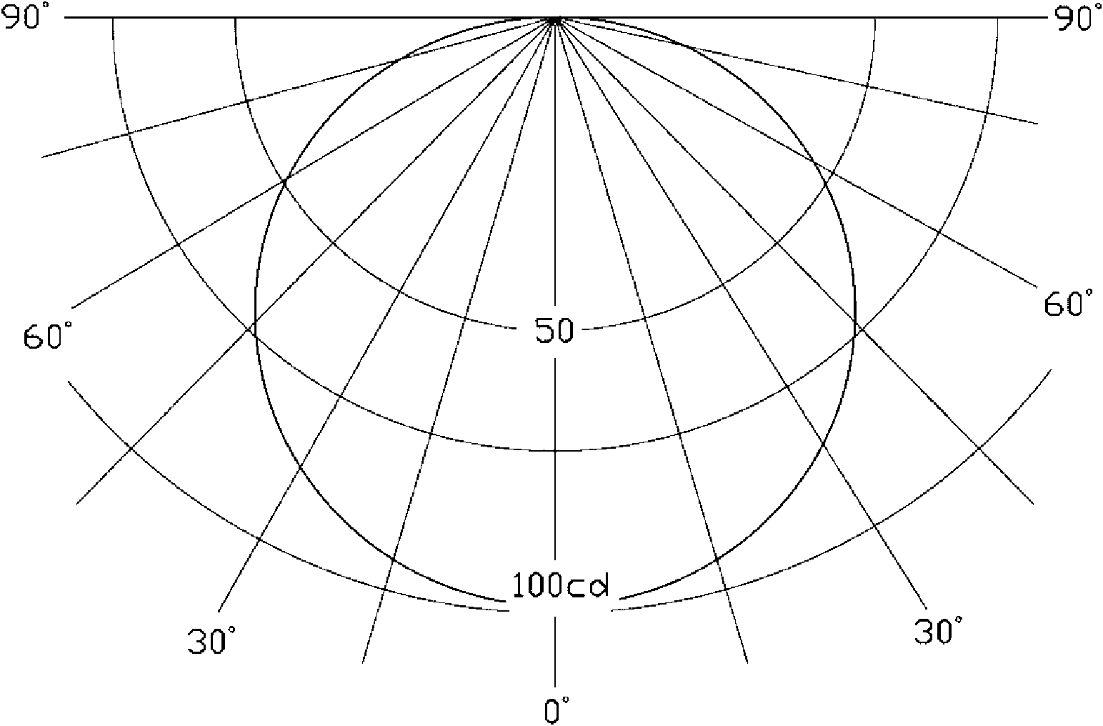
At the same time, the light distribution curve of the light source cannot be adjusted according to the change of the area to be illuminated

Method used


Image

  • Illumination system
  • Illumination system
  • Illumination system

Examples


Embodiment Construction

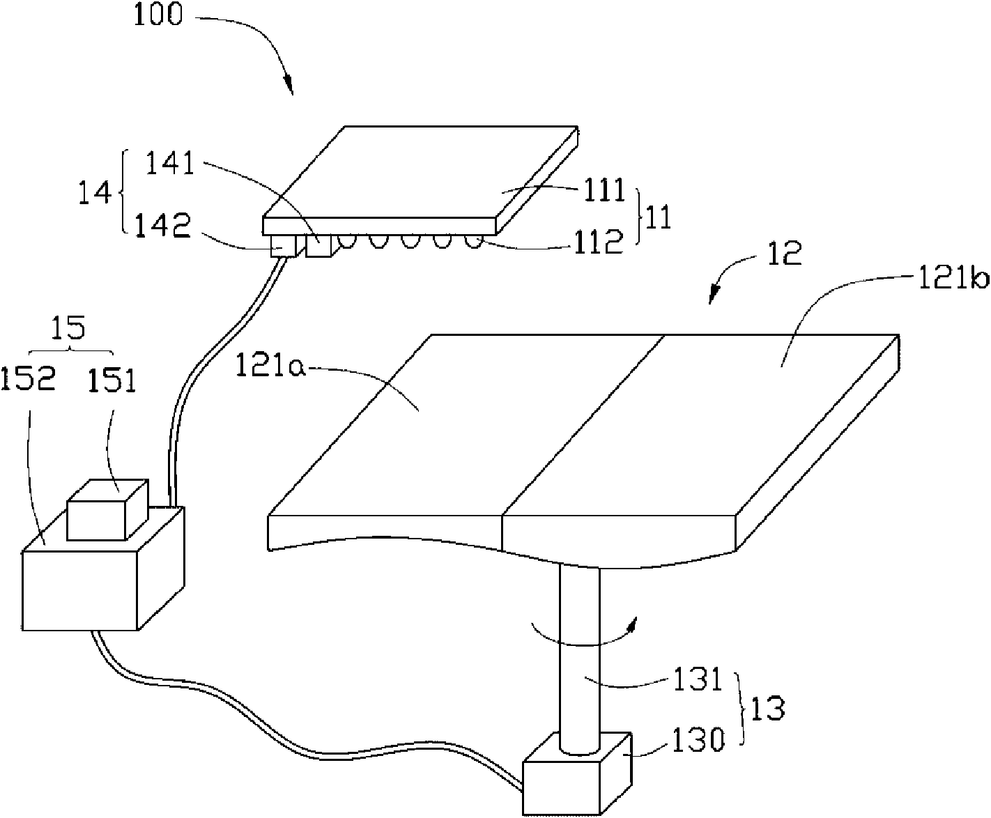
[0020] Please refer to figure 2 , is a schematic structural diagram of the lighting system 100 provided by the first embodiment of the present invention. The lighting system 100 includes a light source 11 , an optical lens 12 , a driving module 13 and a detecting module 14 .

[0021] The light source 11 includes a substrate 111 and a plurality of light emitting elements 112 disposed on the substrate 111 . The surface where the plurality of light emitting elements 112 are located is the light emitting surface of the light source 11 . The light-emitting element 112 can be a fluorescent lamp, a cold-cathode fluorescent lamp, an energy-saving lamp, a gas discharge lamp, a halogen lamp, a light-emitting diode chip, a light-emitting diode or a light-emitting diode module.

[0022] The optical lens 12 is opposite to the light emitting surface of the light source 11 . The optical lens 12 is flat and includes two lens units 121a and 121b. The lens unit 121a is a plano-concave lens...


PUM


Abstract

An illumination system comprises a light source, an optical element, a sensing module and a driving module, wherein the optical element is provided with a plurality of light transmission parts; light emitted from the light source generates corresponding distribution curve fluxes after passing through each light transmission part; the sensing module is used for sensing an area to be illuminated and outputting a sensing signal; and the driving module is used for driving the optical element to move in a space according to the sensing signal output by the sensing module so as to make the light emitted from the light source emergent from one light transmission part of the optical element.

Description

technical field [0001] The invention relates to an illumination system, in particular to an illumination system capable of adjusting the light distribution curve of a light source according to the area to be illuminated. Background technique [0002] Light Emitting Diode (LED, Light Emitting Diode) has the advantages of high brightness, low operating voltage, low power consumption, easy matching with integrated circuits, simple driving, and long life, so it can be used as a light source and widely used in the lighting field. For details, please refer to Joseph Bielecki et al. wrote Thermal Considerations for LED Components in an Automotive Lamp in the 2007 IEEE, 23rd IEEE SEMI-THERM Symposium. A light emitting diode is a semiconductor element that converts electrical current into light of a specific wavelength range. [0003] The light distribution curve of the so-called light source indicates the distribution of the light emitted by the light source in space. The light di...

Claims


Application Information

Patent Timeline
IPC IPC(8): F21S2/00F21V23/00F21V14/06F21V5/04H05B37/02F21Y101/02
CPCF21V14/06H05B33/0842F21V5/002F21V14/006F21V23/0442F21Y2101/02F21Y2115/10H05B45/00
Inventor 赖志铭
Owner JIANGSU ZHONGKE GLOBALTEK OPTOELECTRONICS LIGHT ENERGY
Learn More