

Back light module, driving method thereof and liquid crystal display
A technology of a backlight module and a driving method, which is applied to static indicators, optics, instruments, etc., can solve the problems of high driving power consumption, high cost, low light utilization rate, etc., so as to reduce driving power consumption, reduce quantity, and save cost effect
- Summary
- Abstract
- Description
- Claims
- Application Information
AI Technical Summary
Problems solved by technology
Method used
Image

Examples
no. 1 example
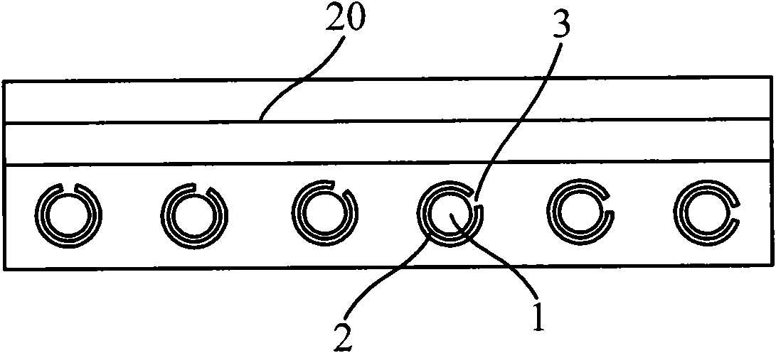
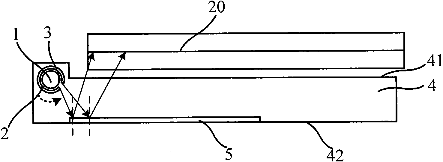
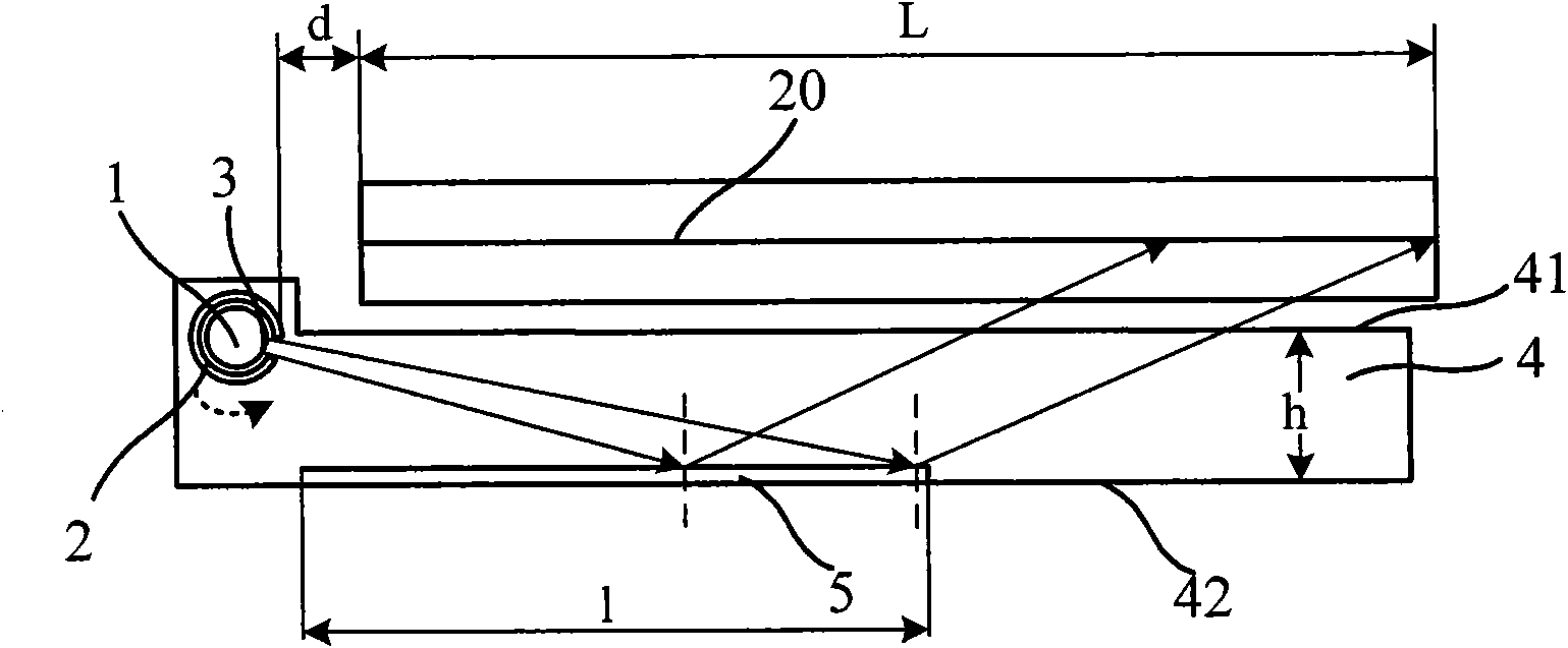
[0031] figure 2 It is a structural representation of the first embodiment of the backlight module of the present invention Figure 1 . Such as figure 2 As shown, the backlight module includes: a light guide cavity 4 , a backlight source 1 , a grating cover 2 and a reflector 5 . Wherein, the light guide cavity 4 includes a back plate 42, and the surface on the side opposite to the back plate 42 in the light guide cavity 4 is the light output surface 41 of the light guide cavity 4. When the backlight module is assembled into the liquid crystal display, the light output surface 41 is Adjacent to the liquid crystal panel 20 and parallel to d, the light emitting surface 41 is an imaginary surface corresponding to the light incident surface of the liquid crystal panel 20; the backlight source 1 is arranged on the side of the light guide cavity 4; the grating cover 2 is arranged on the backlight source 1 On the outside, the grating cover 2 is provided with at least one grating s...
no. 2 example
[0037] Figure 4 It is a structural schematic diagram of the second embodiment of the backlight module of the present invention. The difference between this embodiment and the first embodiment is that there are multiple reflecting mirrors 5 arranged at intervals on the back plate 42 , and the reflecting mirrors 5 in this embodiment are plane mirrors. Preferably, there is an acute angle between the plane where each reflector 5 is located and the back plate 42 .
[0038] The working principle of the backlight module of this embodiment is: the backlight source 1 emits constant light, and the scanning beam emitted from the grid slit 3 is irradiated on the backplane 42; At a certain angle, the scanning beam can be reflected out of the light guide cavity 4, such as Figure 4 As shown; the grating cover 2 rotates around the backlight source 1 at a set speed. With the rotation of the grating cover 2, the position of the grid slit 3 changes, and the scanning beam can move on the back...
PUM
 Abstract
Description
Claims
Application Information