
Torque measurement device

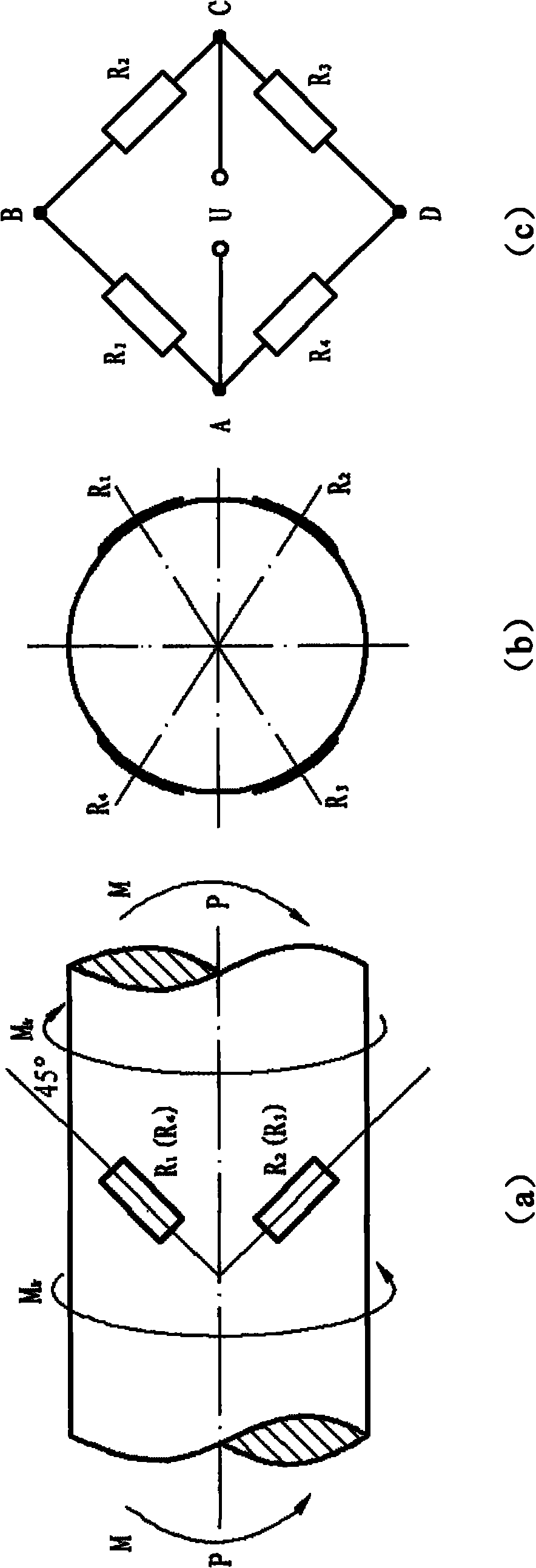
A torque measurement, stepped shaft technology, applied in the field of torque measurement devices, can solve problems such as poor signal-to-noise ratio, unavoidable errors, and wear of contact parts, achieve simple on-site installation and torque testing operations, reduce on-site work, and avoid testing. effect of error

Inactive Publication Date: 2010-10-06
CHINA AGRI UNIV
View PDF0 Cites 14 Cited by
  • Summary
  • Abstract
  • Description
  • Claims
  • Application Information

AI Technical Summary

Problems solved by technology

[0006] 1. Slip rings, brushes, etc. are used as current collectors in the collector ring. The high-speed rotation of the shaft will easily cause wear and local overheating of the contact parts, and the signal-to-noise ratio of the signal is relatively poor, which affects the working life.
So this method is not suitable for high-speed rotating shaft
[0007] 2. Every time a rotating shaft is tested, the strain gauge must be pasted again, and it cannot be repeatedly applied to other measured shafts.
The placement process is cumbersome to operate, and errors are unavoidable
[0008] 3. Agricultural machinery often swings up and down or left and right when working in the field. If the transmission universal joint and the power output shaft are installed or used improperly, the shaft head of the power output shaft will often be broken and the universal joint will be damaged.

Method used


Image

  • Torque measurement device
  • Torque measurement device
  • Torque measurement device

Examples


Embodiment Construction

[0028] The following examples are used to illustrate the present invention, but are not intended to limit the scope of the present invention.

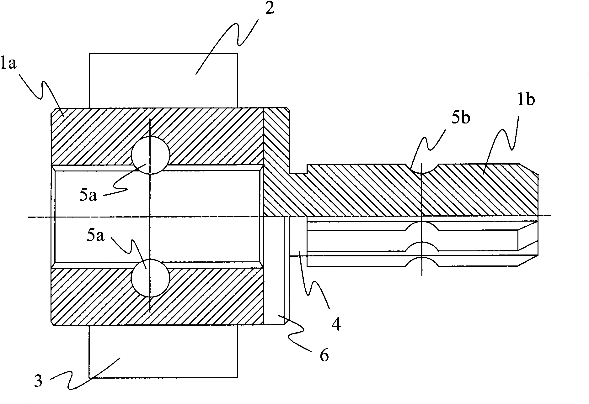
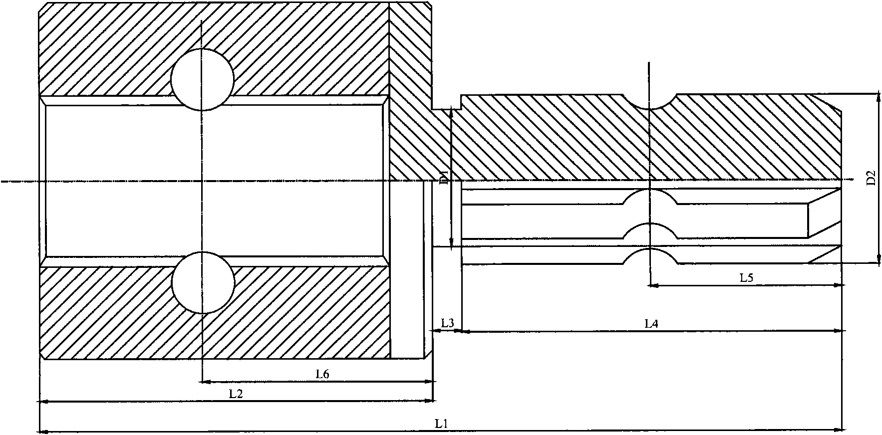
[0029] Such as figure 2 As shown, the torque measuring device of this embodiment comprises: a shaft sleeve 1a, a stepped shaft 1b welded to the shaft sleeve 1a, an inductive element, a wireless transmitting unit and a conditioning unit 2, and a power supply unit 3. The shaft sleeve 1a is a cubic metal body with an internal hollow structure, the hollow structure has internal splines, and the cross-sectional shape of the internal splines matches the cross-sectional shape of the external splines of the power output shaft of the power device to be connected. The height H1 of the inner spline = the outer spline addendum circle diameter φD of the power output shaft of the tractor and other power devices under test EE +(20~30mm); Width B1=Outer spline addendum circle diameter φD of the power output shaft of the tractor and other power devic...


PUM


Abstract

The invention relates to a torque measurement device, which comprises a stepped shaft, a sensing element, a shaft sleeve, a conditioner unit and a wireless transmission unit, wherein the stepped shaft is divided into a paster part and a part provided with an external spline along the axial direction of the stepped shaft; the sensing element is arranged at the paster part of the stepped shaft; the shaft sleeve is connected with the stepped shaft and is of a hollow shape internally, and the hollow structure is provided with an internal spline; the conditioner unit and the wireless transmission unit are all arranged at the upper side of the shaft sleeve and are connected with a full bridge converter; the conditioner unit is used for converting the voltage output by the full bridge converter into a digital signal the amplitude of which corresponds to the torsion thereof; and the wireless transmission unit is used for transmitting the digital signal. The invention greatly reduces the fieldwork of torque measurement, does not need to replace the existing device, and does not need to carry out polishing, cleaning and foil gauge sticking and bridge forming and the like on a measured shaft, thereby enabling the field installation and torsion measurement operation to be much simpler, avoiding the measurement error caused by field foil gauge sticking, and being recycled.

Description

technical field [0001] The invention relates to a torque measuring device for a rotating shaft of a power machine, in particular to a torque measuring device for a power output shaft of a power device such as a tractor. Background technique [0002] The power take-off shaft of the tractor is used to drive the seeder, fertilizer applicator, harvester, rotary tiller and stationary work equipment, etc. GB-T 1592.3-2008 stipulates the type and size of the shaft head of the rear power take-off shaft of agricultural tractors. Torque, also known as torque, is one of the important working parameters of the power output shaft (see GB / T 3871.3-2006 for testing standards). By measuring the torque of each transmission shaft, it can provide a reference for the determination and control of the transmission shaft load, so as to avoid the situation of "big horse and small cart". [0003] At present, the most widely used method for measuring the torque of the rotating shaft is the strain m...

Claims


Application Information

Patent Timeline
IPC IPC(8): G01L3/04
Inventor 王书茂伍建成罗瑞龙
Owner CHINA AGRI UNIV
Learn More