D-type flip-flop unit and frequency divider with the same

A technology of triggers and frequency dividers, applied in the direction of electrical components, automatic power control, pulse generation, etc., can solve the problems of slow speed, inability to realize the programmable frequency division number, etc., to reduce circuit complexity and reduce tape-out The effect of using area and structure is simple

Inactive Publication Date: 2010-10-06
SHANGHAI INTEGRATED CIRCUIT RES & DEV CENT
View PDF4 Cites 17 Cited by
  • Summary
  • Abstract
  • Description
  • Claims
  • Application Information

AI Technical Summary

Problems solved by technology

But it can only switch between two frequency division numbers, and cannot realize a wider range of frequency division number programmable
The latter has the disadvantage of slow speed

Method used


Image

  • D-type flip-flop unit and frequency divider with the same
  • D-type flip-flop unit and frequency divider with the same
  • D-type flip-flop unit and frequency divider with the same

Examples


Embodiment Construction

[0014] The specific implementation manners of the present invention will be described in further detail below with reference to the accompanying drawings. Throughout the description, like reference numerals refer to like parts.

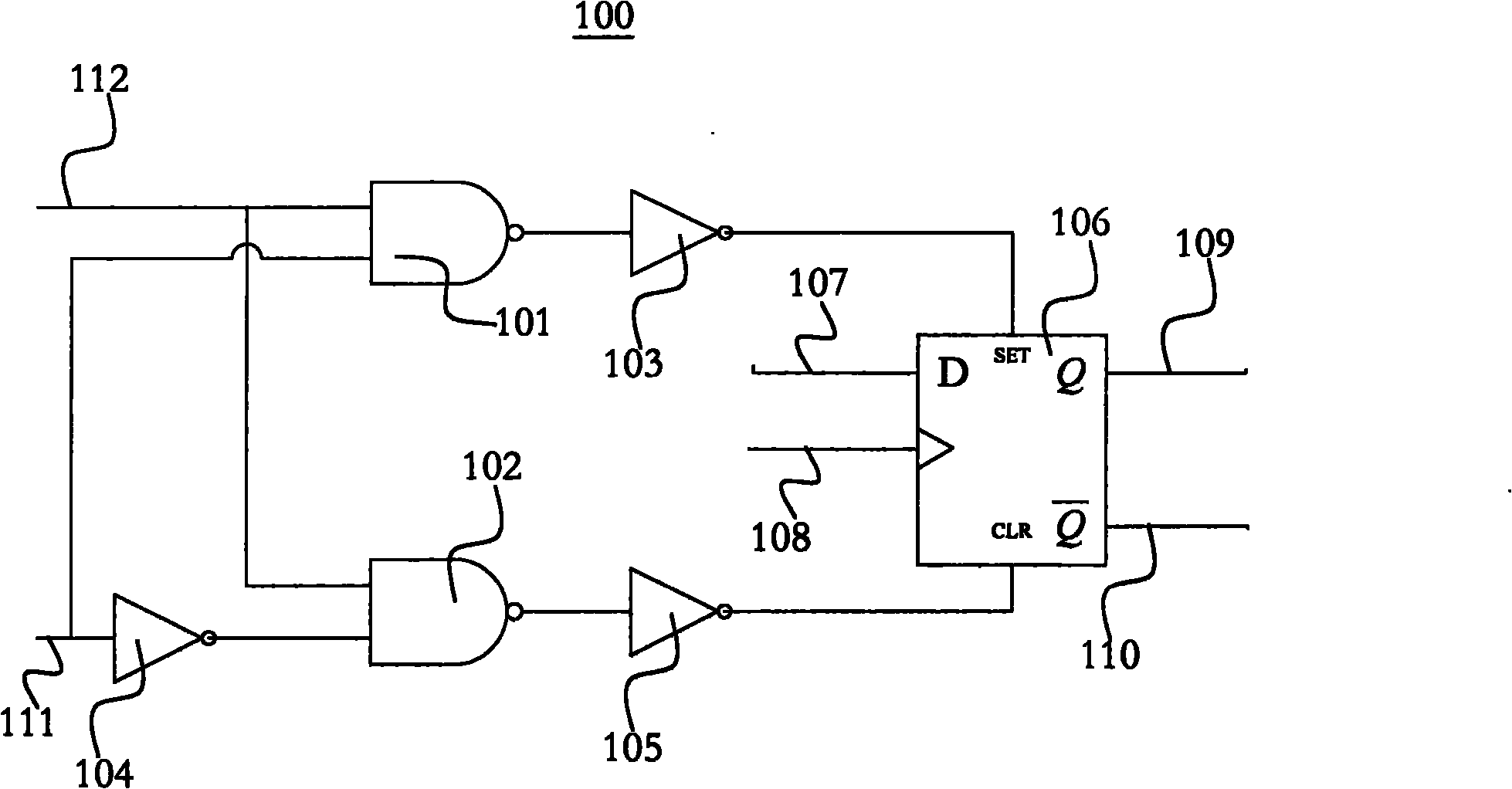
[0015] figure 1 It is a schematic diagram of the circuit structure of a D-type flip-flop unit. refer to figure 1 , D-type flip-flop unit 100 includes: a first two-input NAND gate 101, a second two-input NAND gate 102, a first inverter 103, a second inverter 104, a third inverter 105, and a second inverter 103 A D-type flip-flop 106 .

[0016] The data control end 107 of the first D-type flip-flop 106 is the data control end of the D-type flip-flop unit 100, and the clock signal input terminal (CLK) 108 of the first D-type flip-flop 106 is the clock signal of the D-type flip-flop unit 100 Input end, the non-inverting output end 109 of the first D-type flip-flop 106 is the non-inverting output end of the D-type flip-flop unit 100, and the inverting ...


PUM


Abstract

The invention provides a D-type flip-flop unit, which comprises a first two-input NAND gate, a second two-input NAND gate, a first inverter, a second inverter, a third inverter and a first D-type flip-flop. The invention also provides a frequency divider with the D-type flip-flop unit, which can input a frequency dividing number through a group of N-bit binary digital signals M, and the input frequency is divided by M +1 to generate an output frequency. The frequency divider with the D-type flip-flop unit comprises N cascading D-type flip-flop units, a logic gate circuit, and an internal reset circuit. The D-type flip-flop unit can use fewer devices to realize more complex circuit, and reduces circuit complexity and flow use area. The multi-bit programmable and modular frequency divider can divide frequency for any one integer ranging from 1 to 2N, and can meet the requirements of high-speed RF circuit and simple structure.

Description

technical field [0001] The invention relates to the technical field of wireless transceiver circuits, in particular to a frequency divider in a phase-locked loop. Background technique [0002] In order to achieve high-quality radio communication and reduce the interference of various external factors on the transmission signal, modern communication systems often require the communication machine to have a large number of carrier frequency oscillation signals that can be selected and quickly replaced by users, and frequency synthesis technology can achieve A circuit technique for the above requirements. It is suitable for advanced electronic systems such as space communication radar measurement, telemetry remote control, satellite navigation and digital communication. At present, the most widely used is the frequency synthesis technology based on phase-locked loop, which can synthesize very high frequency, and at the same time, the phase noise is relatively small. Difficult...

Claims


Application Information

Patent Timeline
Patent Type & Authority Applications(China)
IPC IPC(8): H03K3/037H03L7/18
Inventor 任铮胡少坚周伟曹永峰顾学强王勇
Owner SHANGHAI INTEGRATED CIRCUIT RES & DEV CENT
Why Eureka
Try Eureka