Lithium rechargeable cell with reference electrode for state of health monitoring

A technology for reference electrodes and lithium-ion batteries, applied in secondary battery charging/discharging, small-sized batteries/battery packs, secondary batteries, etc., can solve problems such as discomfort, insufficient stability and lifespan

Active Publication Date: 2010-10-06
A123 SYSTEMS LLC
View PDF7 Cites 60 Cited by
  • Summary
  • Abstract
  • Description
  • Claims
  • Application Information

AI Technical Summary

Problems solved by technology

Existing reference electrodes such as lithium metal may not be suitable for use in Li-ion battery systems with the above requirements due to insufficient stability and lifetime (e.g. drift of the reference potential) or unsuitable reference potential

Method used


Image

  • Lithium rechargeable cell with reference electrode for state of health monitoring
  • Lithium rechargeable cell with reference electrode for state of health monitoring
  • Lithium rechargeable cell with reference electrode for state of health monitoring

Examples


example 1

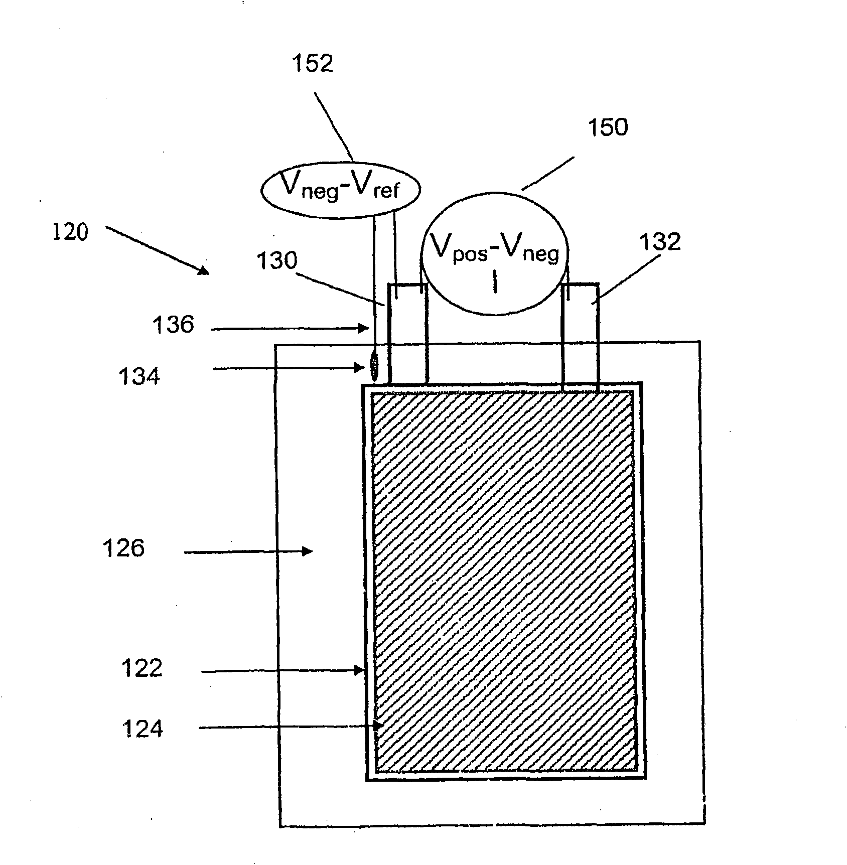
[0128] Example 1. Li-ion prismatic cell using a Li reference electrode

[0129] Such as Figure 5 As shown, a prismatic cell is made by stacking a negative electrode 522 , a separator 526 , and a positive electrode 524 . Copper wire 536 , which is insulated except at the end, is placed adjacent to (but not in electrical contact with) negative electrode 522 so that it is covered by separator 526 but not between the active regions of anode 530 and cathode 532 . Lithium metal 534 is then crimped over the exposed end of the copper wire. The battery is filled with electrolyte (LiPF in carbonate solvent mixture 6 ) and be sealed. The cells were subjected to a number of conditioning cycles at room temperature, then placed in a Tenney temperature chamber and brought to -20°C. Batteries were cycled on an Arbin battery cycler. Figure 6 The voltage curves of such a battery during charging from a 50% state of charge at different charge rates (0.3C, 0.5C, 0.7C, 1C and 1.5C) and then ...

example 2

[0131] Example 2. Using Li 4 Ti 5 o 12 (LTO) Li-ion prismatic cells with reference electrodes

[0132] Example A: By coating an area of ​​a piece of copper foil with Li 4 Ti 5 o 12 (LTO) paste, binder and conductive additives, then allow the paste to dry, date the application, and cut the foil into narrow strips, apply LTO to one end of each strip, thereby making a reference electrode . The uncoated portion of the copper strip is insulated with tape to create a barrier to electrolyte contact. The prismatic cell was assembled as described in Example 1 with the additional step of placing a fourth electrode on top of the separator covering the LTO reference electrode, the fourth electrode being made of a lithium-ion phosphate patch. Constructed of Al foil, sized to match the LTO reference electrode. After the cell is filled with electrolyte and sealed, current flows through the auxiliary lithium-ion phosphate electrode and the LTO reference electrode to activate the LTO r...

example 3

[0136] Example 3. Cylindrical battery using the battery can as the reference electrode terminal

[0137] Such as Figure 7 As shown, a cylindrical battery is fabricated by winding multiple repeating units of negative electrode, separator, and positive electrode.

[0138] An exemplary lithium ion battery includes a battery element having a cathode and an anode separated by a microporous separator wound closely together and disposed in a battery can. A typical spiral electrode secondary battery is Figure 7 shown in . The secondary battery 715 includes an anode sheet 701 including an anode material coated on both sides of an anode current collector; a separator 702; and a cathode sheet 703 including a cathode material coated on both sides of a cathode current collector, The anode sheet 701 , the separator 702 and the cathode sheet 703 have been stacked in the order described above and wound to form a spiral shape 709 . The cathode sheet 703 includes a current collector lead ...


PUM

PropertyMeasurementUnit
thicknessaaaaaaaaaa

Abstract

A battery management system includes one or more lithium ion cells in electrical connection, each said cell comprising: first and second working electrodes and one or more reference electrodes, each reference electrode electronically isolated from the working electrodes and having a separate tab or current collector exiting the cell and providing an additional terminal for electrical measurement; and a battery management system comprising a battery state-of-charge monitor, said monitor being operable for receiving information relating to the potential difference of the working electrodes and the potential of one or more of the working electrodes versus the reference electrode.

Description

technical field [0001] This application relates to monitoring the state of charge and / or the state of health of a battery. More specifically, the present application relates to batteries, battery monitoring systems, and methods of improving battery performance by monitoring state of charge and / or state of health of the battery. [0002] Cross References to Related Applications [0003] This application claims the benefit of the filing dates of U.S. Patent Application No. 60 / 993,802, filed September 14, 2007, and U.S. Patent Application No. 60 / 994,089, filed September 17, 2007, the entire contents of which are incorporated by reference here. Background technique [0004] State-of-charge (SOC) monitoring is desired or necessary in many battery applications, including portable electronics such as wireless communication devices and laptop computers, power tools, electric vehicles (including hybrid, plug-in Electric vehicles), back-up power systems, energy storage such as sola...

Claims


Application Information

Patent Timeline
Patent Type & Authority Applications(China)
IPC IPC(8): H01M10/42H01M50/55H01M50/553H01M50/559H01M50/562H01M50/566
CPCH01M2/30Y02E60/122H01M10/425Y02T10/7011H02J7/0045H01M10/44Y02T10/7055H01M10/0525H02J7/0068H02J7/0014H02J7/0052G01R31/026H01M10/48H01M50/553H01M50/55H01M50/562H01M50/566H01M50/559Y02T10/70Y02E60/10G01R31/54Y02P70/50G01R31/36H01M4/00H01M4/485H01M50/543H02J7/00
Inventor R·富洛朴Y-M·蒋K·E·托马斯-阿利亚W·H·加德纳
Owner A123 SYSTEMS LLC
Why Eureka
Try Eureka