Device for removing harmful gas from airflow

A technology of harmful gas and air flow, which is applied in the separation of dispersed particles, chemical instruments and methods, separation methods, etc., can solve the problems of complex adsorbent regeneration and subsequent treatment systems, and the inability to decompose harmful gases, so as to improve energy utilization efficiency, The effect of improving purification efficiency

Inactive Publication Date: 2010-10-13
黄立维
View PDF6 Cites 7 Cited by
  • Summary
  • Abstract
  • Description
  • Claims
  • Application Information

AI Technical Summary

Problems solved by technology

The adsorption method has a high removal efficiency for low-concentration pollutants, but it cannot achieve the purpose of decomposing harmful gases. The regeneration of the adsorbent and the subsequent treatment system are complex

Method used


Image

  • Device for removing harmful gas from airflow
  • Device for removing harmful gas from airflow
  • Device for removing harmful gas from airflow

Examples


Embodiment 1

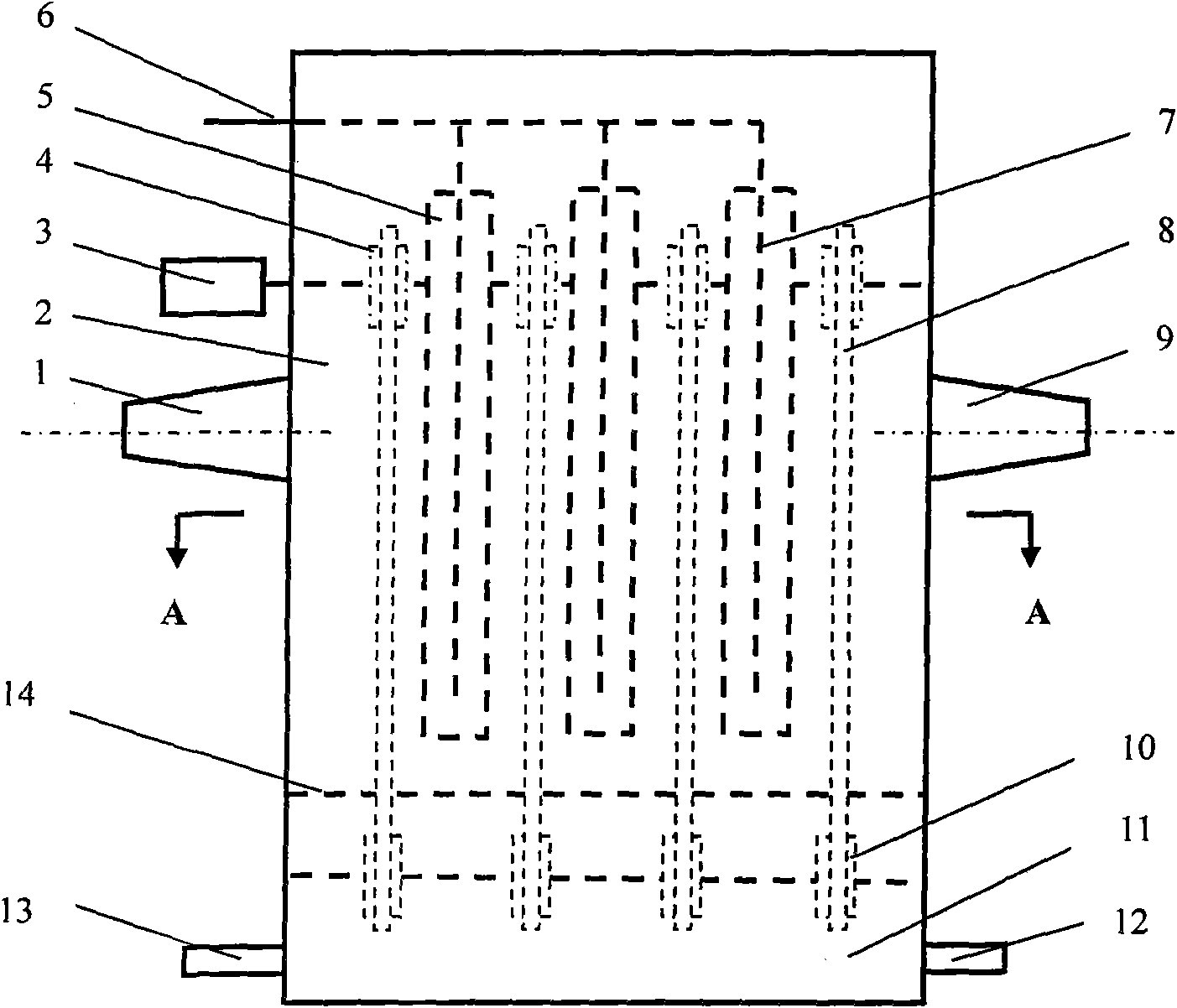
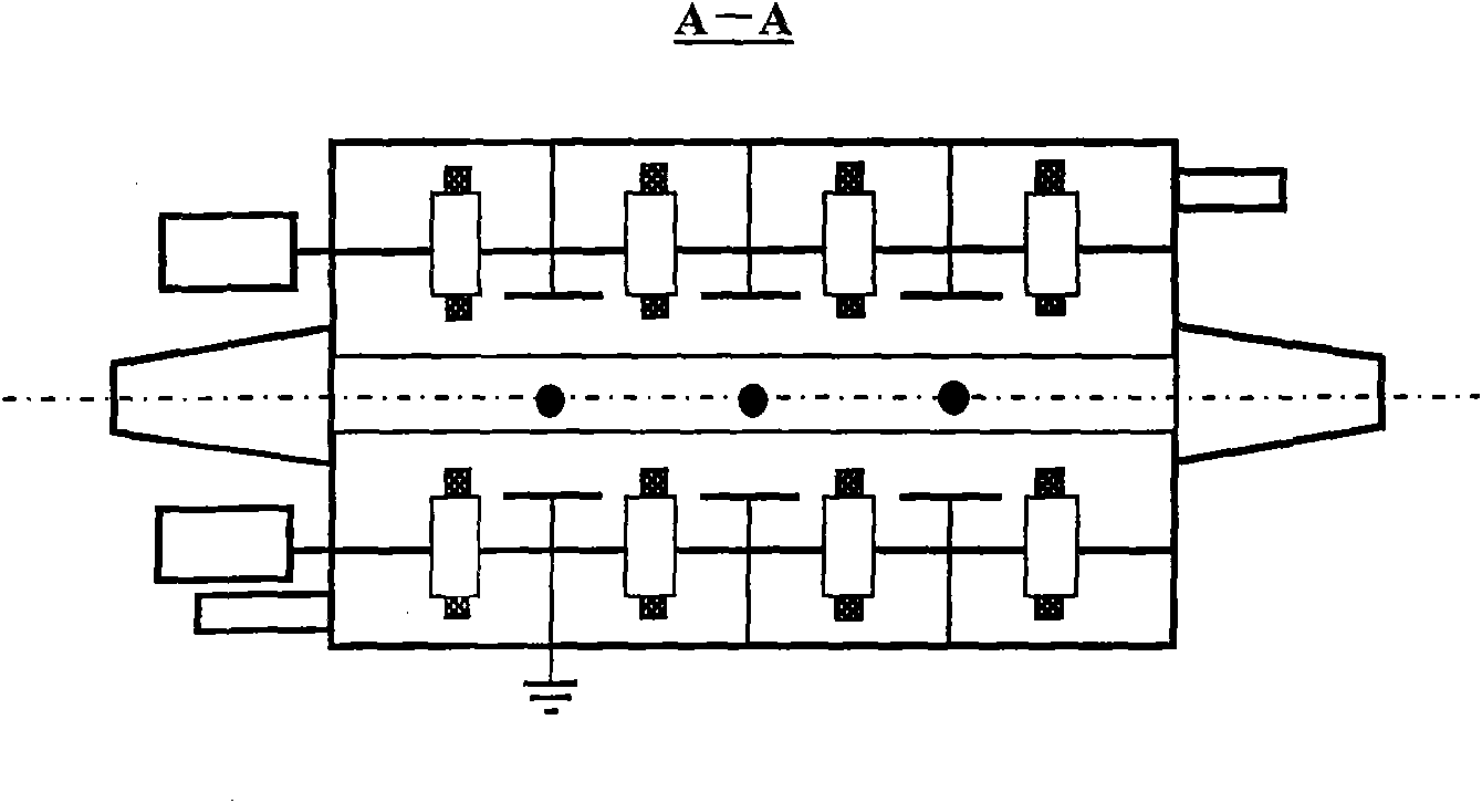
[0019] refer to figure 1 : A purification device for harmful exhaust gas, comprising gas inlet 1, gas circulation space 2, conveyor belt driving motor 3, upper conveyor pulley 4, electrode plate (grounding) 5, corona high voltage wiring 6, corona wire 7, and the surface is for uploading Conveyor belt with absorbent 8, gas outlet 9, lower conveyor pulley 10, absorbent slurry pool 11, absorbent slurry inlet 12, absorbent slurry outlet 13 at the lower part of the device, and partitions between the upper gas circulation space and the absorbent slurry layer 14 apart.

[0020] The treatment process is to introduce the gas containing harmful gas to be treated into the reactor through the gas inlet 1, and the gas flow first passes through the corona discharge area, and under the action of the corona discharge in the reaction area, the harmful gas in the gas flow is oxidized and decomposed. Then in the gas-solid absorption reaction zone, the acidic product in the product reacts with t...

Embodiment 2

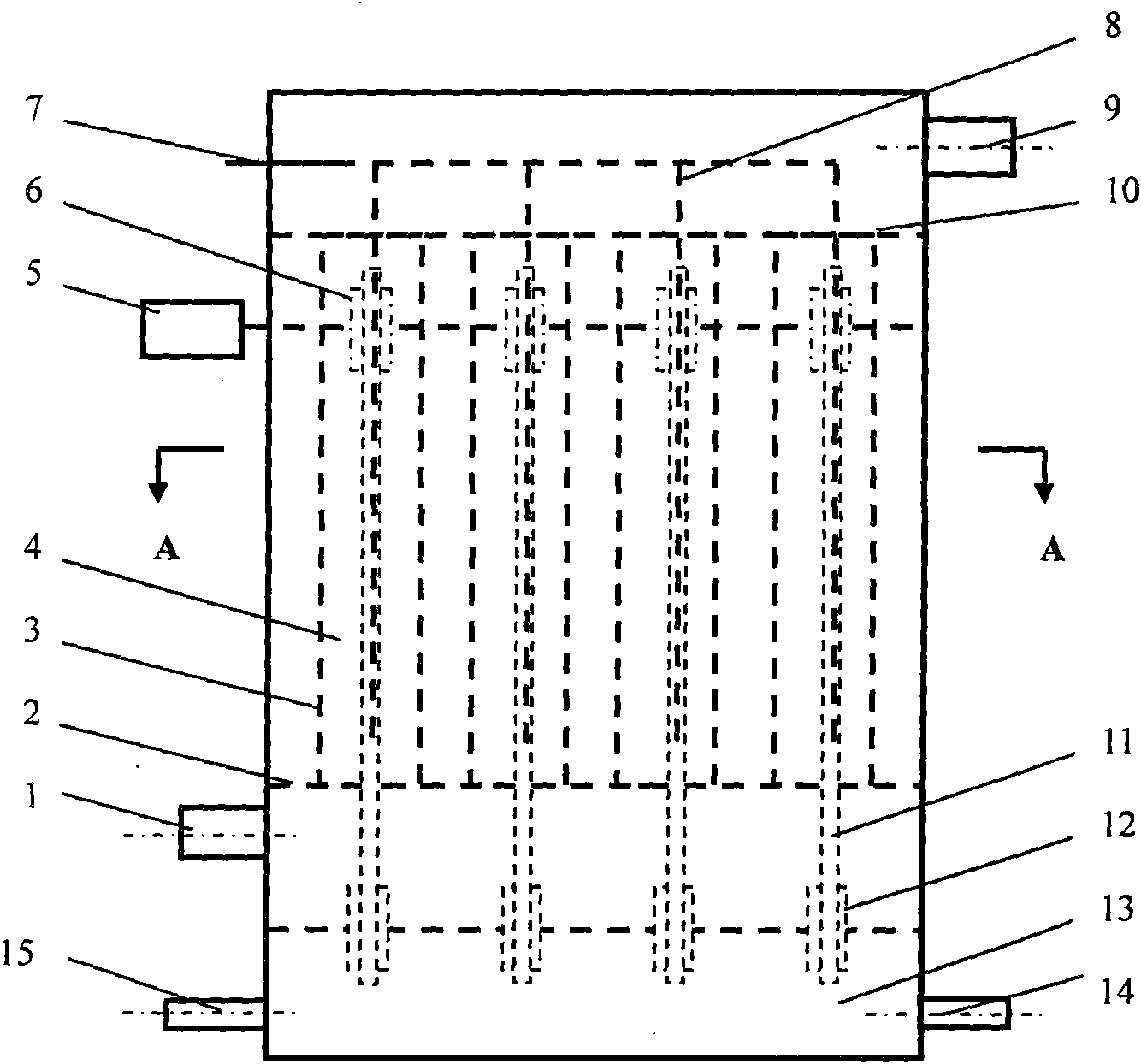
[0031] refer to figure 2 : A purification device for harmful exhaust gas, comprising a gas inlet 1, a lower baffle plate 2, a cylindrical electrode plate 3, a gas circulation space 4, a conveyor belt drive motor 5, an upper conveyor pulley 6, a corona high-voltage connection 7, and a corona wire 8. Gas outlet 9, upper baffle 10, conveyor belt 11 with absorbent on the surface, lower conveyor pulley 12, absorbent slurry pool 13, absorbent slurry inlet 14, absorbent slurry outlet 15 at the bottom of the device.

[0032] The treatment process is to introduce the gas containing harmful gas to be treated into the reactor through the gas inlet 1, and the gas flow flows from bottom to top in the cylinder, and in the flow channel, under the action of corona discharge, the harmful gas in the gas flow is eliminated Oxidation, decomposition, and then in the gas-solid absorption reaction zone, the acidic product in the product reacts with the absorbent and is absorbed by the absorbent. Th...


PUM


Abstract

The invention relates to a device which consists of corona discharge and chemical absorption and is used for removing gaseous harmful substances containing fluorine, chlorine, sulfur or nitrogen and organic gas such as hydrocarbon, alcohol and aldehyde from airflow. The method comprises the following steps that: gas to be processed is firstly guided into a reactor which consists of a corona discharge reaction area and a gas-solid absorption reaction area, so under the effect of the corona discharge non-balance plasma body, while the harmful gas is oxidized and decomposed, acid product in the product can be absorbed by solid absorbent inside the reactor, so the gas can be purified. The absorbent after being saturated is conveyed along a transmission belt to an absorbent pulp tank which is arranged on the lower part of the device, and the absorption layer on the transmission belt is washed and is reloaded with fresh absorbent to be sent back to the reaction area.

Description

technical field [0001] The invention belongs to the technical field of purification methods for removing harmful gases contained in gas streams. Background technique [0002] Industrial production processes such as chemistry, pharmaceuticals and coatings produce various harmful gases, such as gaseous harmful substances (including organic and inorganic substances) containing fluorine, chlorine, sulfur or nitrogen, and organic substances such as hydrocarbons, alcohols and aldehydes. These pollutants are not only harmful to the human body, some are carcinogens, and a large amount of discharge has also had a serious impact on the local area environment, and it is also one of the reasons for the formation of atmospheric photochemical smog. However, these substances have poor water solubility, strong volatility or stable chemical structure and are not easy to degrade, which brings great difficulties to purification. [0003] Other methods to deal with the above pollutants include...

Claims


Application Information

Patent Timeline
Patent Type & Authority Applications(China)
IPC IPC(8): B01D53/75B01D53/82B01D53/96B01D53/68B01D53/72B01D53/60
Inventor 黄立维
Owner 黄立维
Why Eureka
Try Eureka