
Round steel cutter

A cutting machine and round steel technology, which is applied in the direction of shearing devices, shearing machine accessories, shearing machine equipment, etc., can solve the problems of unsatisfactory shearing effect, large section slope, and cutting machine wear, etc., and achieve improvement Process safety, large shear force, and the effect of improving flatness

Inactive Publication Date: 2010-10-13
ZHEJIANG LONGLI MACHINERY
View PDF6 Cites 17 Cited by
  • Summary
  • Abstract
  • Description
  • Claims
  • Application Information

AI Technical Summary

Problems solved by technology

[0002] In the field of metal processing, cutting of metal bars such as round steel is often carried out. The commonly used cutting method is to use a round steel cutting machine to cut the material. The diameter of the round steel is also different. Cutting the round steel with a large diameter The requirements are relatively high, there must be a large shearing force, and the stability of the round steel must be ensured during shearing, because the round steel will vibrate when sheared, and the vibration will cause a large slope of the section and a relatively small roundness. poor, which brings difficulty to subsequent processing; most of the existing round steel cutting machines use motors to drive the rotation, that is, the motor drives the large pulley to rotate, the large pulley drives the gear shaft to rotate, the gear shaft drives the gear to rotate, the gear drives the eccentric shaft to rotate, and the eccentric The shaft drives the connecting seat to move repeatedly, and the connecting seat drives the connecting rod to move. The connecting rod is equipped with a shear blade, which repeatedly moves to cut round steel. The force generated by this cutting machine is small, and it is only suitable for small diameter round steel. Steel shearing, shearing large-diameter round steel not only cannot achieve a satisfactory shearing effect, but also causes severe wear and tear on the cutting machine and shortens its life

Method used


Image

  • Round steel cutter
  • Round steel cutter
  • Round steel cutter

Examples


Embodiment

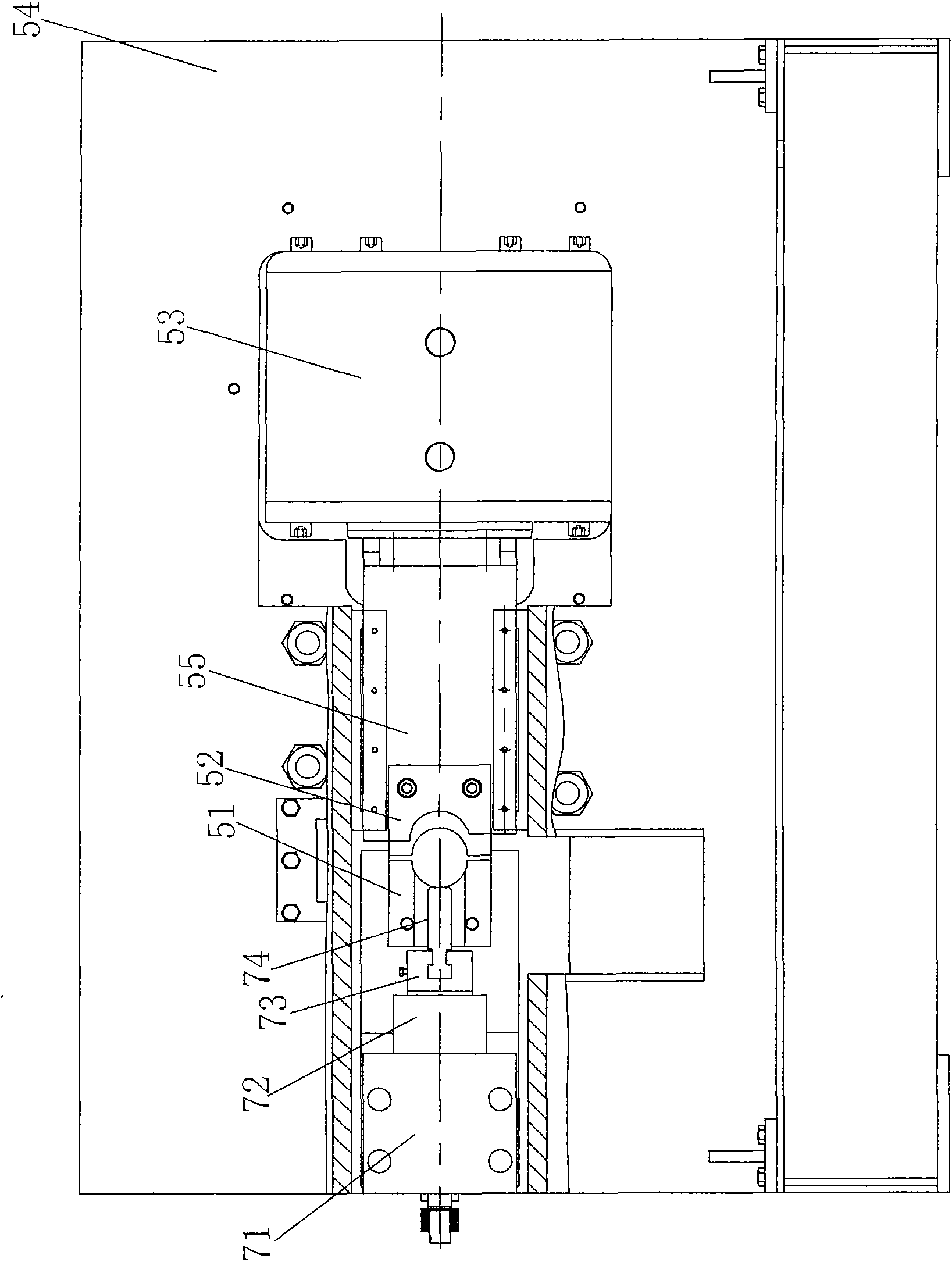
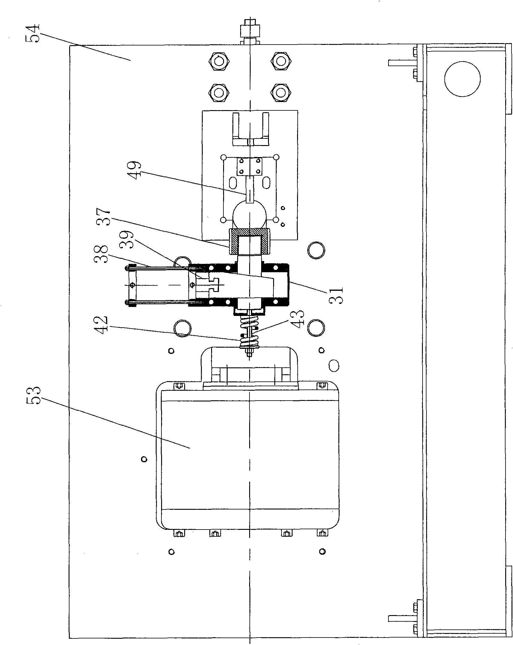
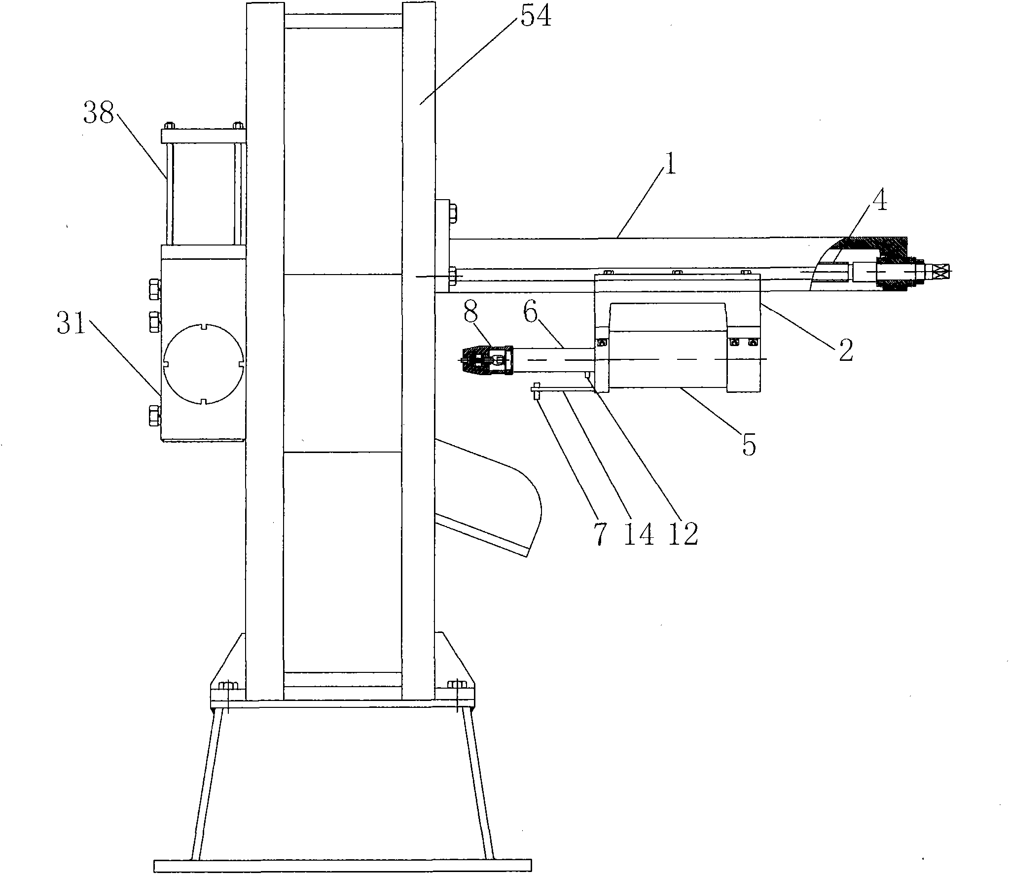
[0034] Embodiment: a kind of round steel cutting machine, as Figure 1-3 As shown, it includes a fixed knife 51, a moving knife 52, and a main oil cylinder 53. The fixed knife 51 is fixed at the cutting opening of the cutting machine body 54, and the moving knife 52 is installed on a moving knife seat 55. The piston rod is connected to each other, and the material inlet and the outlet of the machine body 54 are respectively provided with a pressing device and a material supporting device for clamping the round steel during shearing. The semi-circular hole groove of the round steel is placed, and the moving knife 52 and the fixed knife 51 are staggered. After the round steel is fed into the semi-circular hole groove of the fixed knife 51 through the feeder, the pressing device and the supporting device will clamp the round steel. The movable knife 51 slides on the body 54 under the action of the main oil cylinder 53 to cut material.

[0035] Such as Figure 4 , Figure 5 , ...


PUM


Abstract

The invention discloses a round steel cutter, which comprises a fixed cutter, a movable cutter and a main oil cylinder, wherein the fixed cutter is fixed at a shearing port of the cutter body; the movable cutter is arranged on a movable cutter seat; the movable cutter seat is connected with a piston rod of the main oil cylinder; and a pressing device and a supporting device for clamping round steels during shearing are arranged at a feeding hole and a discharge hole of the cutter body. Because hydraulic pressure is used as shearing power, the shearing force is large, the motion is stable, the noise is low, the shearing process does not produce metal scraps and sparks, and the processing safety is improved. Moreover, the round steel cutter effectively solves the shock produced during shearing the round steels, improves the flatness of round steel sections, improves the processing efficiency, and provides convenience for subsequent processing.

Description

technical field [0001] The invention relates to a round steel cutting machine, in particular to a round steel cutting machine which is suitable for cutting large-diameter round steel and can effectively prevent the round steel from vibrating during cutting. Background technique [0002] In the field of metal processing, cutting of metal bars such as round steel is often carried out. The commonly used cutting method is to use a round steel cutter to cut the material. The diameter of the round steel is also different. Cutting the round steel with a large diameter The requirements are relatively high, there must be a large shearing force, and the stability of the round steel must be ensured during shearing, because the round steel will vibrate when sheared, and the vibration will cause a large slope of the section and a relatively small roundness. poor, which brings difficulty to subsequent processing; most of the existing round steel cutting machines use motors to drive the ro...

Claims


Application Information

Patent Timeline
Patent Type & Authority Applications(China)
IPC IPC(8): B23D15/14B23D15/04B23D33/00B23D33/02
Inventor 张龙弟
Owner ZHEJIANG LONGLI MACHINERY
Learn More