Optical tool regulator for excimer laser micromachining system

An excimer laser and micromachining technology, which is applied in the field of micro-nano science, can solve the problems of low-dimensional adjustment, the inability to use the excimer laser micromachining system optical path, time-consuming and labor-intensive problems, and achieve reliable long-term stable work.

Inactive Publication Date: 2010-10-13
BEIJING UNIV OF TECH
View PDF9 Cites 12 Cited by
  • Summary
  • Abstract
  • Description
  • Claims
  • Application Information

AI Technical Summary

Problems solved by technology

The excimer laser spot size is relatively large, with a diameter of about 30X15mm. Therefore, components in the optical path, such as beam shaping components and beam homogenizers, must use relatively large diameters, and correspondingly require relatively large-sized support components. The supporting parts of the optical devices that can be used on the optical bench of the laboratory are all small in size and cannot be used for the needs of the optical path of the excimer laser micromachining system
At the same time, many square optical elements are used in the beam transformation components of the excimer laser micromachining system, such as the application of cylindrical mirrors and square lens arrays used in compound eyes. Introduction to the general method of placing square components of different sizes. The existing method is to customize the installation frame that fully matches the size of the square component that needs to be installed. This method is not only time-consuming and labor-intensive but also a waste of resources in practical applications.
In addition, the general support components currently on the market can only be adjusted in low dimensions, and do not support adjustments in more directions, and cannot be applied to systems that require adjustment in multiple directions, which greatly affects the debugging of the general support components. accuracy
In the excimer laser micromachining system, the optical path support components with larger diameters are used. Due to their large size and heavy weight, after the necessary optical path adjustment, only the fine-tuning screw drive and tension spring It is impossible to guarantee the reliable and long-term stable operation of the micromachining system. It must have an independent structure to fasten the optical components in the micromachining system after the optical path debugging is completed. However, the general support components on the market do not have the design idea of ​​fastening the optical components at all. And the specific structure, there is no literature report on the application of this structure in the field of excimer laser micromachining system
In the excimer laser micromachining system, it is necessary to turn the beam from the horizontal direction to the vertical direction. Even if the optical path is turned 90° to microprocess the material, and because the optical components used in the excimer laser micromachining system are all large in size, the quasi Fine fine-tuning and long-term stability of large-scale optical components in molecular laser micromachining systems are very important, but the turning components currently on the market cannot perform optical path turning under the premise of ensuring fine fine-tuning and long-term stability

Method used


Image

  • Optical tool regulator for excimer laser micromachining system
  • Optical tool regulator for excimer laser micromachining system
  • Optical tool regulator for excimer laser micromachining system

Examples


Embodiment Construction

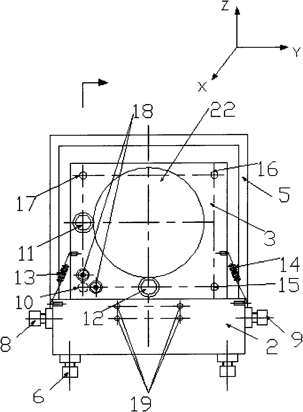
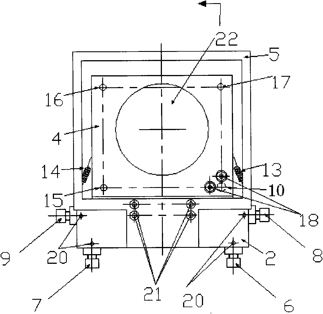
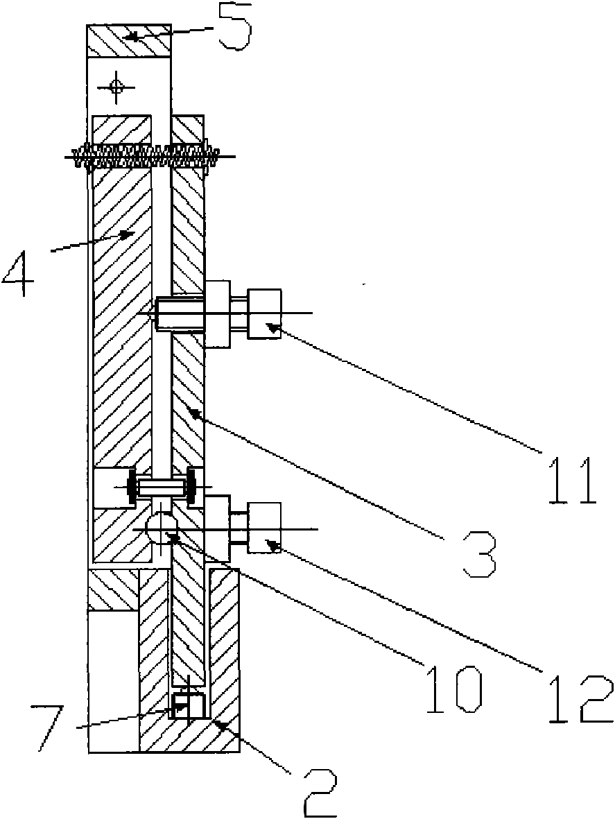
[0024] Combine below figure 1 , figure 2 , image 3 , Figure 4a ~b describes Embodiment 1 of the present invention in detail.

[0025]The present embodiment mainly includes sliding seat 1, adjusting seat 2, support plate 3, mirror frame 4, tight locator 5, reflective inclined frame seat 32, fixes a reflective mirror with it in the present embodiment. The sliding seat 1 is placed on a common optical guide rail, and the reflective inclined frame seat 32 and the sliding seat 1 are provided with three corresponding screw holes, which are connected by bolts and nuts. Four fixed screw holes 21 are established on the side of the adjustment seat 2, and three screw holes are established on its bottom surface, and four screw holes and three screw holes are also respectively correspondingly established on the two faces of the inclined groove of the reflective inclined frame seat 32, and are connected with the adjustment seat. The side and bottom surface of 2 are connected by bolts ...


PUM

PropertyMeasurementUnit
diameteraaaaaaaaaa

Abstract

The invention relates to an optical tool regulator for an excimer laser micromachining system, which belongs to the technical field of micro-nanoscale science and is used for MEMS machining. In the optical tool regulator, a sliding seat (1) is arranged on an optical guide rail; a regulating seat (2), a supporting plate (3), a mirror bracket (4) and a tight positioner (5) are sequentially arranged on the sliding seat (1); the mirror bracket (4) is provided with an optical tool hole (22) capable of accommodating a circular optical element with heavy caliber; and a square optical element regulator (23) arranged in the optical tool hole (22) and a light-reflecting inclined frame seat (32) capable of converting light paths are arranged. The optical tool regulator can realize five-dimensional fine adjustment in the X direction, Y direction, Z direction, pitching direction and the direction of left and right rotation, and also can convert the light paths by 90 degrees and is provided with square optical elements. The tight positioner (5) is directly connected with the regulating seat (2), and coats the periphery of the mirror bracket (4), a plurality of screw holes are uniformly formed at the periphery of the lateral surface of the tight positioner, and the tight positioner butts against the mirror bracket (4) fixedly through bolts, so that the optical elements work reliably and stably for a long time.

Description

technical field [0001] The invention relates to an optical adjustment and tight positioner of an excimer laser micromachining system and a large-size square optical element placement method, which belongs to the field of micro-nano science and technology and is used for MEMS processing. Background technique [0002] Excimers are complexes of two homonuclear or heteronuclear atoms of the most chemically active inert elements Ar, Kr, and Xe and the most chemically active elements F, Cl, and Br in an excited state. Unlike ordinary molecules, an excimer is a molecule that is bound in an electronically excited state. It has no stable ground state. That is, an excimer is an unstable molecule that can only exist temporarily in an excited state. It will dissociate rapidly in the ground state. into other molecular groups, so the lifetime of the excimer is very short, and its upper energy level lifetime is only 10 -8 s, and the lower energy level of the laser transition is a weakly b...

Claims


Application Information

Patent Timeline
Patent Type & Authority Applications(China)
IPC IPC(8): G02B7/00B23K26/08
Inventor 吴坚李倩陈涛刘世炳
Owner BEIJING UNIV OF TECH
Why Eureka
Try Eureka