
PWM (Pulse-Width Modulation) complementary output method of inserting variable dead zone time

A dead time, PWM signal technology, applied in the direction of converting AC power input to DC power output, output power conversion devices, electrical components, etc., can solve problems such as complex methods and many gates

Inactive Publication Date: 2012-08-08
SHANDONG UNIV
View PDF0 Cites 1 Cited by
  • Summary
  • Abstract
  • Description
  • Claims
  • Application Information

AI Technical Summary

Problems solved by technology

Its logic implementation uses an adder, a subtractor, and multiple comparators to realize the insertion of variable dead time. This logic implementation method is more complicated, and the number of gates used is relatively large, which has a negative impact on cost reduction.

Method used


Image

  • PWM (Pulse-Width Modulation) complementary output method of inserting variable dead zone time
  • PWM (Pulse-Width Modulation) complementary output method of inserting variable dead zone time
  • PWM (Pulse-Width Modulation) complementary output method of inserting variable dead zone time

Examples


Embodiment

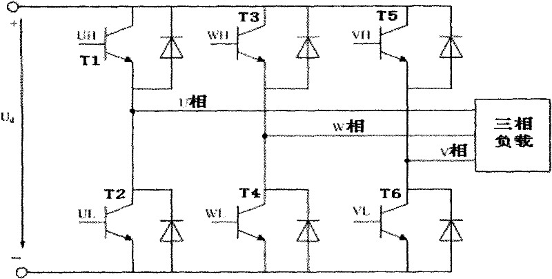
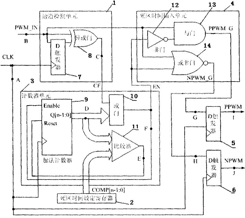
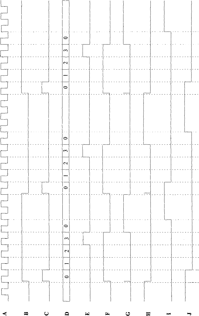
[0023] Examples of the present invention Figure 1-2As shown, a PWM complementary output method that inserts variable dead time, it is realized by three groups of identical control circuits, wherein each group of control circuits includes edge detection unit 1, dead time setting register 2, counter Unit 3, dead time insertion unit 4 and first D flip-flop 5 and second D flip-flop 6 that output complementary PPWM and NPWM signals; edge detection unit 1 includes third D flip-flop 7 and exclusive OR gate 8, PWM input The input end of the signal is respectively connected to the data input end of the third D flip-flop 7 and an input end of the XOR gate 8, and the clock signal CLK input end is connected to the clock input end of the third D flip-flop 7, and the third D flip-flop 7 The data output terminal of the addition counter 9 is connected to the other input terminal of the XOR gate 8; The counter unit 3 includes an addition counter 9, an OR gate 10 and a comparator 11, and the o...


PUM


Abstract

The invention relates to a PWM (Pulse-Width Modulation) complementary output method of inserting variable dead zone time, which belongs to a control technology of a three-phase bridge type inverter circuit and is realized by three groups of same control circuits. Each group of circuit comprises an edge detecting unit, a dead zone time setting register, a counting unit, a dead zone time inserting unit and two D triggers for outputting complementary signals. The edge detecting unit firstly detects a PWM input signal, and generates an edge change mark signal CF when the waveform changes. A 'or' relation is established among phases of an output value of a counter, and then a 'or' relation is established with the CF to obtain an enabling control signal of the counter. In the counter unit, whena counted value is equal to a set value, the counted value is synchronized and reset to 0. The dead zone time inserting unit modifies the PWM input signal according to EN (European Norm), the dead zone is inserted into the PWM input signal, and burr is eliminated by the D trigger to obtain a complementary PWM signal to output. The invention has simple circuit, and is suitable to be integrated to a microcontroller provided with a PWM waveform generator, and the dead zone time can be adjusted in a wide range.

Description

Technical field [0001] The invention relates to a PWM complementary output method for inserting variable dead time, and belongs to the technical field of three-phase bridge inverter circuit control. Background technique [0002] PWM is the abbreviation of Pulse Width Modulation, that is, pulse width modulation. It is a very effective technology that uses the digital output of the microprocessor to control the analog circuit. It is widely used in many fields from measurement, communication to variable frequency power supply and control. in the field. [0003] In the sinusoidal pulse width modulation (SPWM) frequency conversion circuit, the most used is such as figure 1 The three-phase bridge inverter circuit shown is composed of six inverter tubes (IGBT) to form a three-phase inverter bridge. During the inverter process, the complementary PWM signal controls the two inverter tubes of the same bridge arm to always It is in the state of being alternately turned on and off, ta...

Claims


Application Information

Patent Timeline
Patent Type & Authority Patents(China)
IPC IPC(8): H02M7/537
Inventor 李惠军吴胜龙
Owner SHANDONG UNIV
Learn More