Transceiver module based on time division duplex and processing method thereof
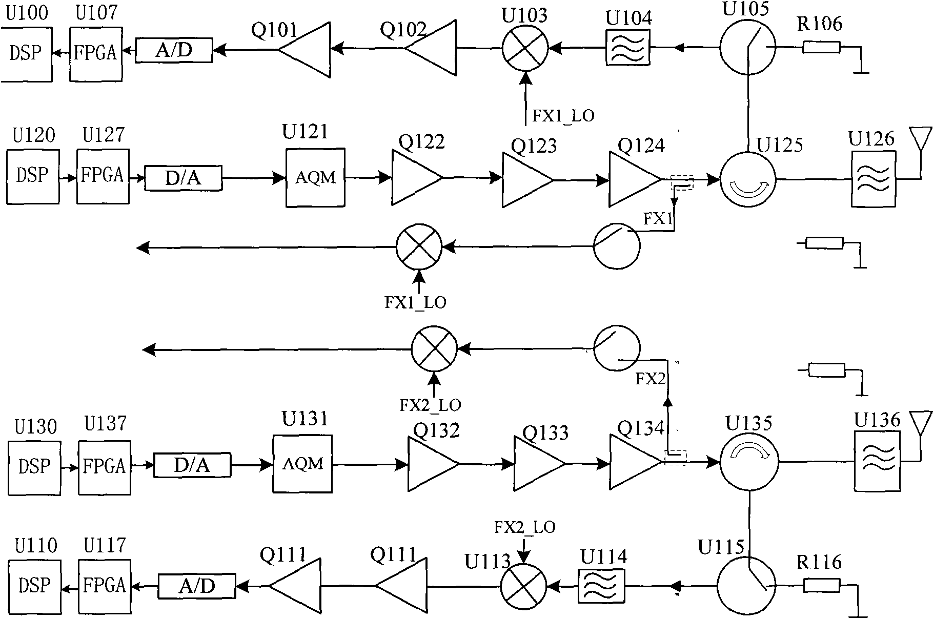
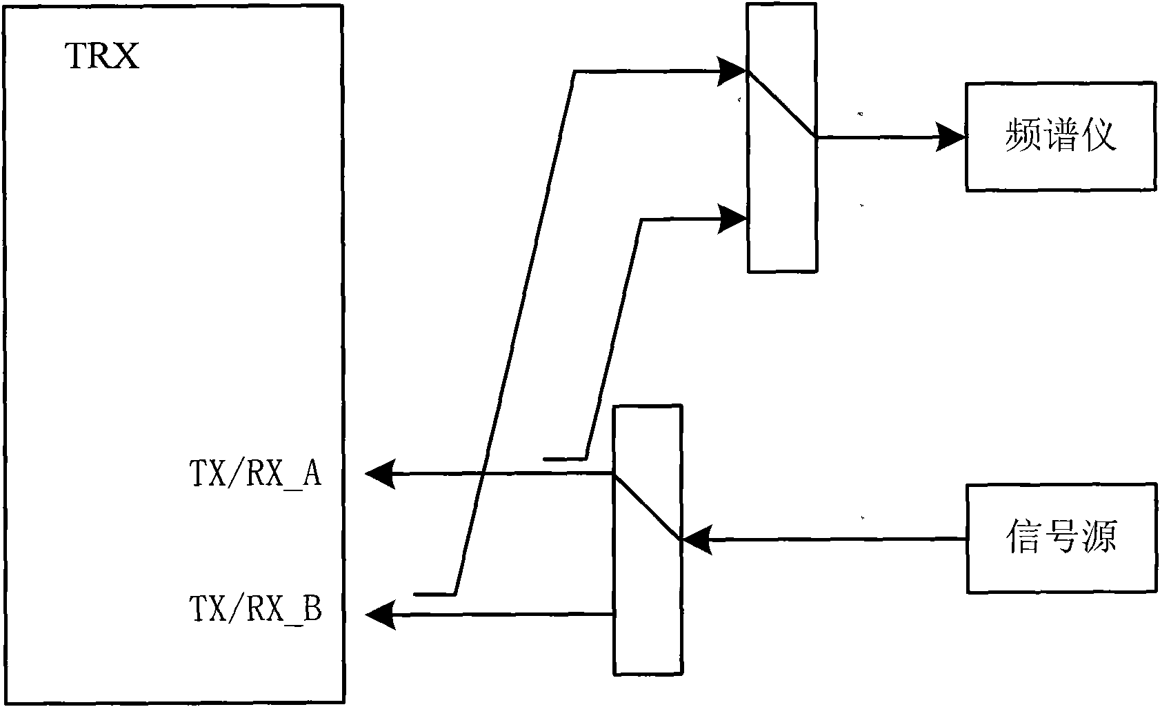
A transceiver and time-division duplex technology, which is applied in the field of communication, can solve the problems that the transmission channel and the receiving channel cannot cooperate to obtain test data, there is no feedback signal test signal circuit structure, and the test efficiency is low.
- Summary
- Abstract
- Description
- Claims
- Application Information
AI Technical Summary
Problems solved by technology
Method used
Image
Examples
Embodiment 1
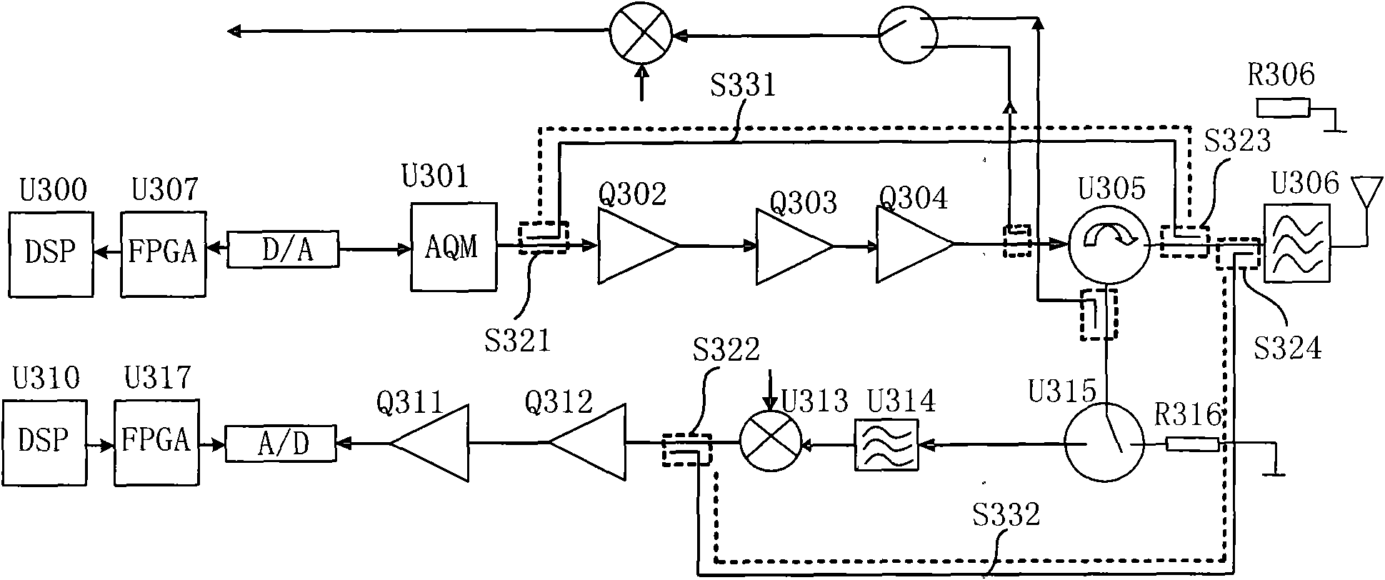
[0029] This embodiment one provides a transceiver module based on Time Division Duplex (TDD, Time Division Duplex), which is used in a TDD-based transceiver, and can be a single-receive, single-transmit transceiver module, or a multiple Receive multi-transmitter transceiver module, the following is as follows image 3 The shown transceiver module of single-receipt and single-transmit is described as an example. The transceiver module of single-receive and single-transmit specifically includes:
[0030] Transmitting channel circuit, receiving channel circuit and RF built-in self-loop circuit;
[0031] Wherein, the transmitting channel circuit is used for transmitting radio frequency signals;
[0032] The receiving channel circuit is used to receive radio frequency signals;
[0033] The radio frequency built-in self-loop circuit is connected between the transmitting channel circuit and the receiving channel circuit, as a closed-loop circuit for the transmitting channel circuit...
Embodiment 2
[0054] The transceiver module based on Time Division Duplex (TDD, Time Division Duplex) provided by this embodiment two is basically the same structure as the transceiver module in embodiment one, the difference is that in the radio frequency built-in self-loop circuit, through Set the resistance power dividing circuit U431, reduce a coupler, and form a Figure 4 In the circuit structure shown, the radio frequency built-in self-loop circuit specifically includes: three couplers S421, S422, S423 and a resistance power dividing circuit U431;
[0055] Wherein, the first coupler S423 is arranged at the signal output end after the circulator U405 of the transmitting channel circuit, and is connected with the second coupler S422 arranged on any input node of the receiving channel circuit through the resistance power dividing circuit U431 in turn, which can Coupling the signal output by the circulator U405 of the transmitting channel circuit into the receiving channel circuit;
[00...
Embodiment 3
[0062] The transceiver module based on time division duplexing provided by the third embodiment, such as Figure 5 As shown, it is a double-receiving and double-transmitting transceiver module. The radio frequency built-in self-loop circuit in the transceiver module of this structure can adopt the structure in embodiment one or embodiment two, as long as the transmission channel circuit The output port of the receiving channel circuit is connected with any input node of the receiving channel circuit and any output node before the output port of the transmitting channel circuit, and a closed loop circuit can be formed between the transmitting channel circuit and the receiving channel circuit, but in order to ensure The circuit is simple and easy to control and match, often using Figure 5 In the circuit structure given in , wherein, the structure of the radio frequency built-in self-loop circuit is based on the radio frequency built-in self-loop circuit of Embodiment 2, adding ...
PUM
 Abstract
Description
Claims
Application Information
 - R&D
- Intellectual Property
- Life Sciences
- Materials
- Tech Scout
- Unparalleled Data Quality
- Higher Quality Content
- 60% Fewer Hallucinations
Browse by: Latest US Patents, China's latest patents, Technical Efficacy Thesaurus, Application Domain, Technology Topic, Popular Technical Reports.
© 2025 PatSnap. All rights reserved.Legal|Privacy policy|Modern Slavery Act Transparency Statement|Sitemap|About US| Contact US: help@patsnap.com


