Control method of breathing machine and control system applicable to same

A control system and control method technology, applied in the direction of respirators, etc., can solve the problems of not being able to ensure the life safety of patients 100% and wasting time, and achieve the effects of ensuring stability and continuity, ensuring life safety, and saving time

Active Publication Date: 2010-10-20
上海力申科学仪器有限公司
View PDF3 Cites 9 Cited by
  • Summary
  • Abstract
  • Description
  • Claims
  • Application Information

AI Technical Summary

Problems solved by technology

But no matter how timely the manual monitoring is, a lot of time will be wasted for self-checking and parameter input during reset, so that the patient's life safety cannot be guaranteed 100%

Method used


Image

  • Control method of breathing machine and control system applicable to same
  • Control method of breathing machine and control system applicable to same
  • Control method of breathing machine and control system applicable to same

Examples


Embodiment 1

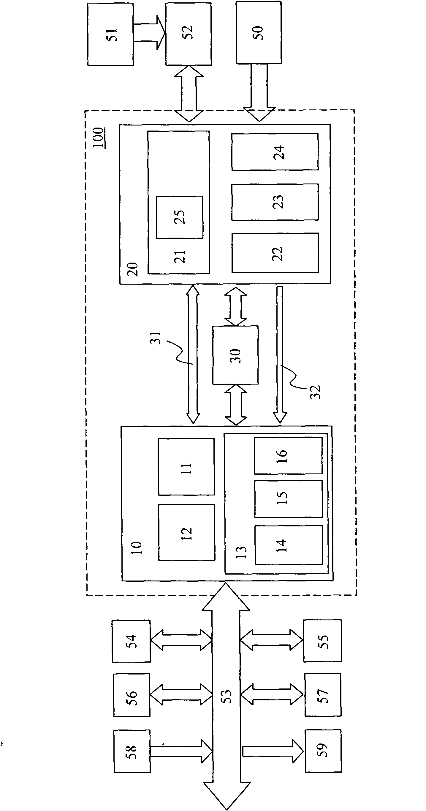
[0036] attached figure 1 It is a block diagram of the control system 100 for the ventilator of the first embodiment.

[0037] as attached figure 1 As shown, the control system 100 includes an ARM microcontroller 10 , a PIC microcontroller 20 and a data buffer 30 .

[0038] The ARM microcontroller 1 is a 32-bit RISC architecture system with high operating speed, strong data processing capability, and strong external expansion capability. Therefore, it is the main CPU in the control system 100 and is responsible for processing most complex events. Peripheral devices such as external RAM 54 , external ROM 55 , display driver 56 , data flash memory 57 , expansion input port 58 and expansion input port 59 are hung on the ARM microcontroller 10 through bus 53 .

[0039] PIC single-chip microcomputer 20 is an 8-bit single-chip microcomputer, and its operating speed is relatively slow, so it is used as a subordinate CPU in the system, responsible for processing a small number of sim...

Embodiment 2

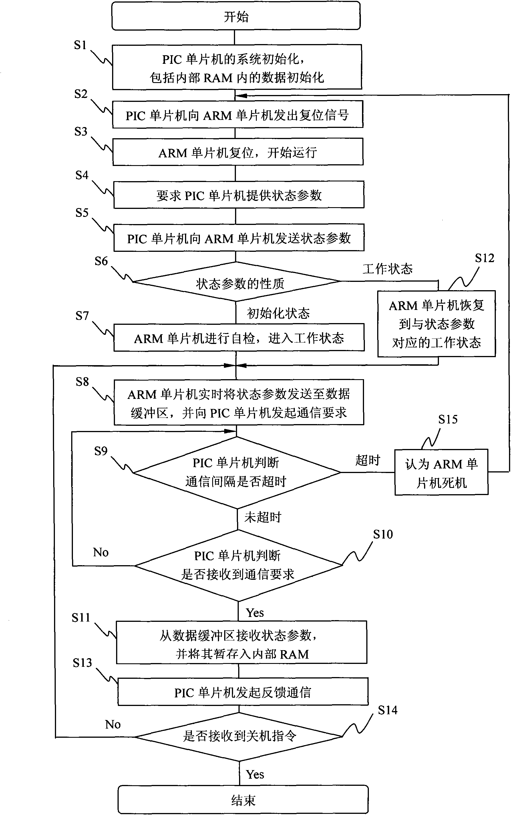
[0066]In the foregoing, although it has been proved through experiments that the PIC microcontroller 20 will hardly crash due to external interference, it does not mean that the PIC microcontroller 20 will never crash. Just in case PIC single-chip 20 crashes, then in the embodiment, owing to adopt RAM as memory, and the data stored in RAM loses power immediately, these data all can be initialized when PIC single-chip 20 resets every time. Therefore, just in case PIC single-chip microcomputer 20 also resets because of crash, then will cause ARM single-chip microcomputer 10 to also enter power-on reset mode thereupon, not only needs to carry out power-on self-check, but also can't recover to the working state before reset.

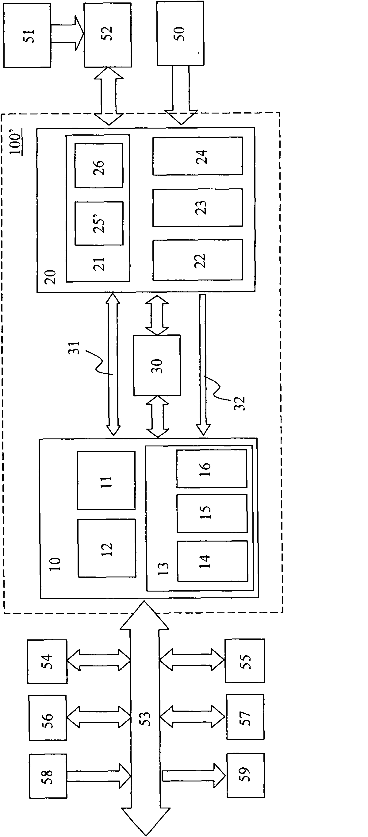
[0067] In order to further solve the above problems, as attached image 3 As shown, in the control system 100' of Embodiment 2, the memory in the storage module 21 is changed from internal RAM 25 to EEPROM 25', that is, an electrically erasable programmable ...


PUM


Abstract

The invention discloses a control method of a breathing machine and a control system applicable to the same. The control system is provided with a first singlechip and a second singlechip. The first singlechip communicates with the second singlechip and sends operation parameters to the second signlechip, wherein the communication time interval does not exceed a preset value. When the first singlechip is reset, the second singlechip is required to return the operation parameters first, and then the working state of the first singlechip is set according to the operation parameters to restore the first singlechip to the state before a dead halt. The second singlechip receives and stores the operation parameters from the first singlechip, and at the same time, monitors the communication time interval to see if the communication time interval exceeds the preset value, and if the communication time interval exceeds the preset value, sends a resetting signal to the first signlechip so as to allow the first singlechip to reset. In the invention, the first singlechip, after resetting from the dead halt, can restore the state before the dead halt directly according to feedback operation parameters without self-checking, so time is saved, working continuity is ensured and life safety of the patient is assured.

Description

technical field [0001] The invention relates to a control method for a ventilator and a control system applicable to the control, in particular, to a control method and system using a microcomputer. Background technique [0002] A ventilator is a medical device used to support the breathing of patients with insufficient breathing capacity. For example, it is usually used as part of an anesthesia machine to anesthetize the patient during surgery and to perform passive breathing on the anesthetized patient. [0003] At present, almost all ventilators are controlled by microcomputers. For example, a single-chip microcomputer is used to receive the signal from the sensor and the input of the keyboard, perform data calculation, control the frequency and air pressure of ventilation, and process the display of the operation interface, etc. With the advancement of science and technology, the functions that the ventilator can realize are becoming more and more complex. Corresponding...

Claims


Application Information

Patent Timeline
Patent Type & Authority Applications(China)
IPC IPC(8): A61M16/00
Inventor 袁方宋智广
Owner 上海力申科学仪器有限公司
Why Eureka
Try Eureka