Laser brazing clearance compensation method

A technology of brazing gap and compensation method, which is applied in the direction of laser welding equipment, welding equipment, welding equipment, etc., can solve the problems of low pass rate, increase of vehicle production cost, and long adjustment time, so as to improve assembly accuracy and facilitate Promote, adjust simple effects

Inactive Publication Date: 2010-10-20
FAW GROUP +1
View PDF6 Cites 15 Cited by
  • Summary
  • Abstract
  • Description
  • Claims
  • Application Information

AI Technical Summary

Problems solved by technology

In particular, the assembly gap of the welded parts is required to reach a uniform gap of 0 to 0.2 mm in order to ensure the strength and appearance of the weld. However, the single-piece machining accuracy error of the stamping process is -0.5 mm to +0.5 mm, which is difficult to achieve after the parts are assembled. Technical requirements, robot programs and welding parameters are adjusted at least twice a week, and there is no basis for adjustment, and the adjustment time is long
Resulting in low pass rate, long production cycle, and increased production cost of the whole vehicle

Method used


Image

  • Laser brazing clearance compensation method
  • Laser brazing clearance compensation method
  • Laser brazing clearance compensation method

Examples


Embodiment 1

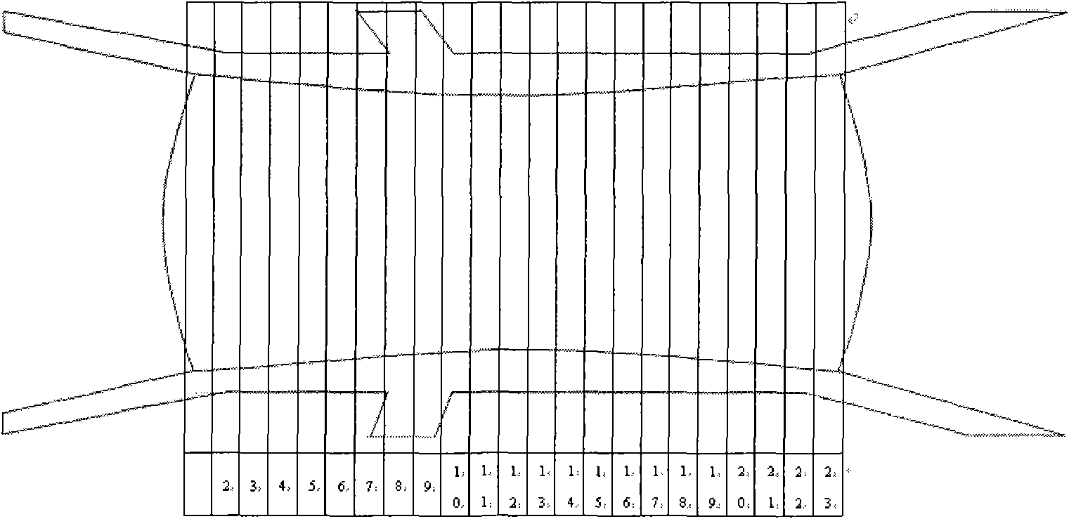
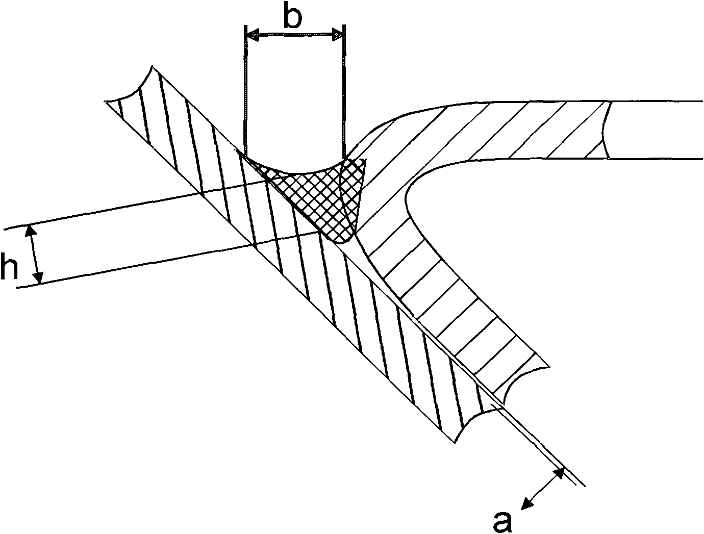
[0015] Such as figure 2 In the assembly area shown, the robot program is decomposed into 23 segments, and segmented control can solve the problem of poor uniformity of the assembly gap. Such as image 3 The shown a is the assembly gap, b is the welding width, and h is the welding penetration depth. By adjusting the robot speed Vb and the wire feeding speed Vs of the hot wire machine, the assembly gap a can be changed to ensure that the welding width b and welding penetration h are stable. . The adjustment range of Vb is less than 2.34 m / min, the adjustment range of Vs is less than 2.88 m / min, the ratio of robot speed Vb to wire feeding speed Vs is (a+b)×k, k is the output loss of the hot wire machine is 0.3525, and the quality requirement of b value is 3mm, by checking such as Figure 4 The table shown to determine the parameters of the robot, such as figure 1 The programmable controller shown in the figure controls the work of the assembly fixture, conveying system, and ...

Embodiment 2

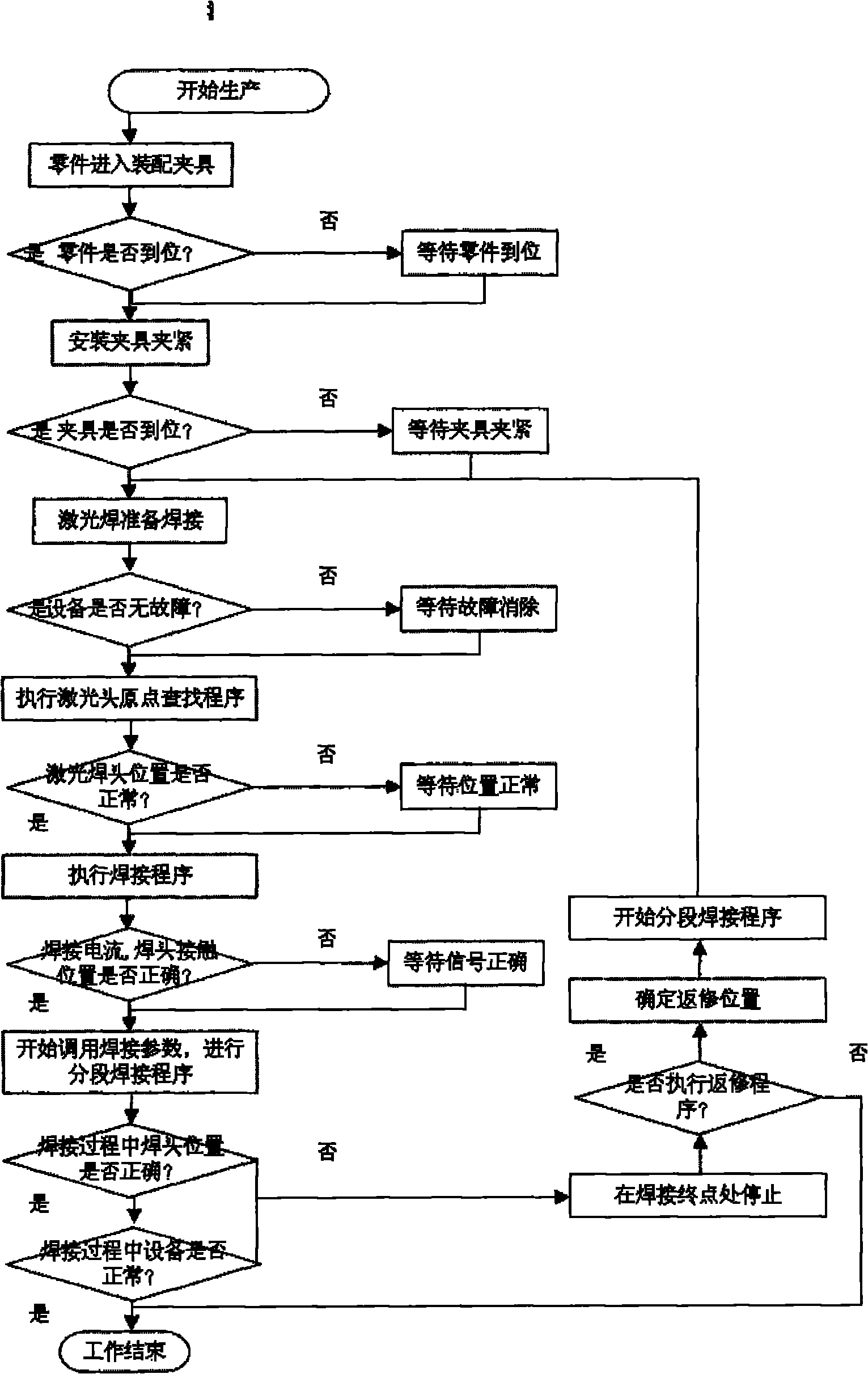
[0019] The programmable controller controls the assembly fixture, conveying system, and robot work, and the robot controls the laser welding machine and laser welding head to work; the parts are transported into the assembly fixture through the conveying system, and the programmable controller detects whether the parts are transported in place and controls the assembly. The fixture is clamped, and the robot controls the laser welding machine to prepare to execute the welding program; execute the laser welding head origin search program to judge whether the position of the laser welding head is correct. If the welding program is performed correctly, if it is not correct, wait for the position to be normal and continue to execute the welding program; after that The system detects whether the welding current and the contact position of the welding head are correct. If the welding parameters are called correctly, the segmental welding is performed; 23 welding procedures are performe...


PUM


Abstract

The invention relates to a laser brazing clearance compensation method. The method is characterized in that: subsection welding program is added into a robot program, twenty three section welding program corresponding is carried out on a welding line with the length of 1.6m, welding parameter is respectively set according to welding condition of each section of the welding line, each section of the welding line is smoothly connected by utilizing the track approaching program of robot, so that the entire three-dimensional arc welding line is smooth in appearance; and a laser welding head origin point search program, a position closed loop control program and a welding line initial point identification program are added into the robot program. The invention requires no modification on mechanical structure, improves assembly accuracy and has low cost; regulating is rapid, thus being applicable to rapid quality control and mass production; and the method is easy to popularize, and adjustment is simple.

Description

Technical field: [0001] The invention relates to a laser brazing gap compensation method, which belongs to the technical field of laser brazing. Background technique: [0002] In order to improve the strength of the car body and reduce the production cost, laser brazing technology is used in the car body manufacturing process. Due to the high quality requirements of laser brazing technology and working conditions on the surface of the car body, the quality of laser brazing is unstable, and the pass rate is only 73%. At the initial stage of production, 10 car bodies in white were scrapped / month, and 8 people were required to modify the surface to improve production. cost. In particular, the assembly gap of the welded parts is required to reach a uniform gap of 0 to 0.2 mm to ensure the strength and appearance of the weld. However, the single-piece machining accuracy error of the stamping process is -0.5 mm to +0.5 mm, which is difficult to achieve after the parts are assembl...

Claims


Application Information

Patent Timeline
Patent Type & Authority Applications(China)
IPC IPC(8): B23K1/005B23K26/20B23K26/42G05B19/05B23K26/21B23K26/70
Inventor 金涛
Owner FAW GROUP
Why Eureka
Try Eureka