
Laser cutting machine and working method thereof

A laser cutting machine and cutting machine technology, applied in laser welding equipment, manufacturing tools, metal processing equipment, etc., can solve the problems of high power consumption, low precision, and non-compliance with industrial requirements of the drive system.

Active Publication Date: 2010-10-20
扬州蝶湖科技产业发展有限公司
View PDF5 Cites 19 Cited by
  • Summary
  • Abstract
  • Description
  • Claims
  • Application Information

AI Technical Summary

Problems solved by technology

The main disadvantages of the heavy main beam are: 1. The heavy weight and large inertia make the dynamic response speed of the main beam movement poor, which has a great impact on the machining accuracy and quality
2. The rigidity of the main beam structure is poor, which will cause a large positioning error of the transmission system
The above two problems make the existing equipment low precision, low quality and low processing efficiency when processing small holes or local complex shapes
When the mass of the moving parts is large, the drive system consumes a lot of power during the working process, which does not meet the current industrial requirements for low-carbon emission reduction

Method used


Image

  • Laser cutting machine and working method thereof
  • Laser cutting machine and working method thereof
  • Laser cutting machine and working method thereof

Examples


Embodiment Construction

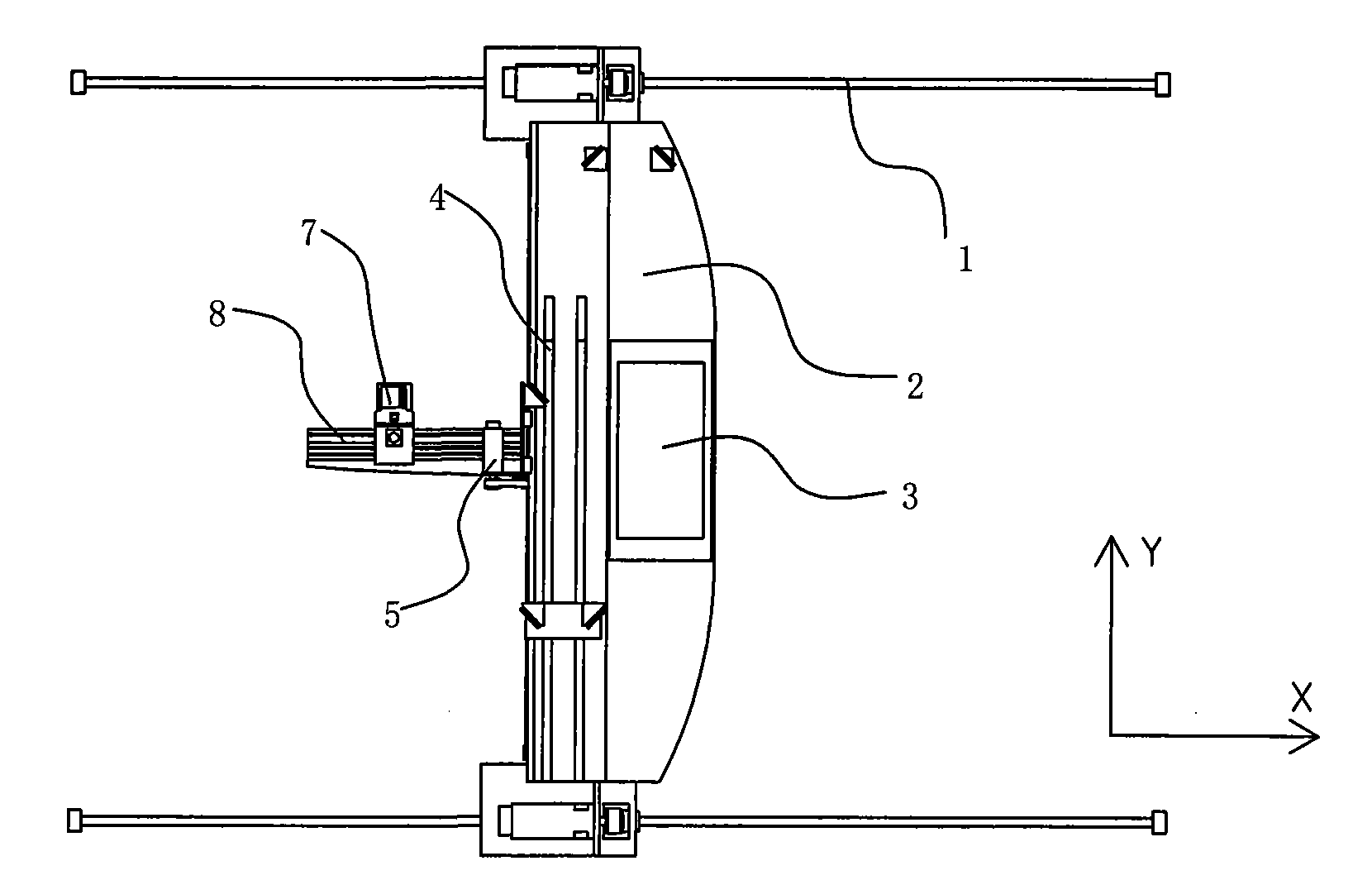
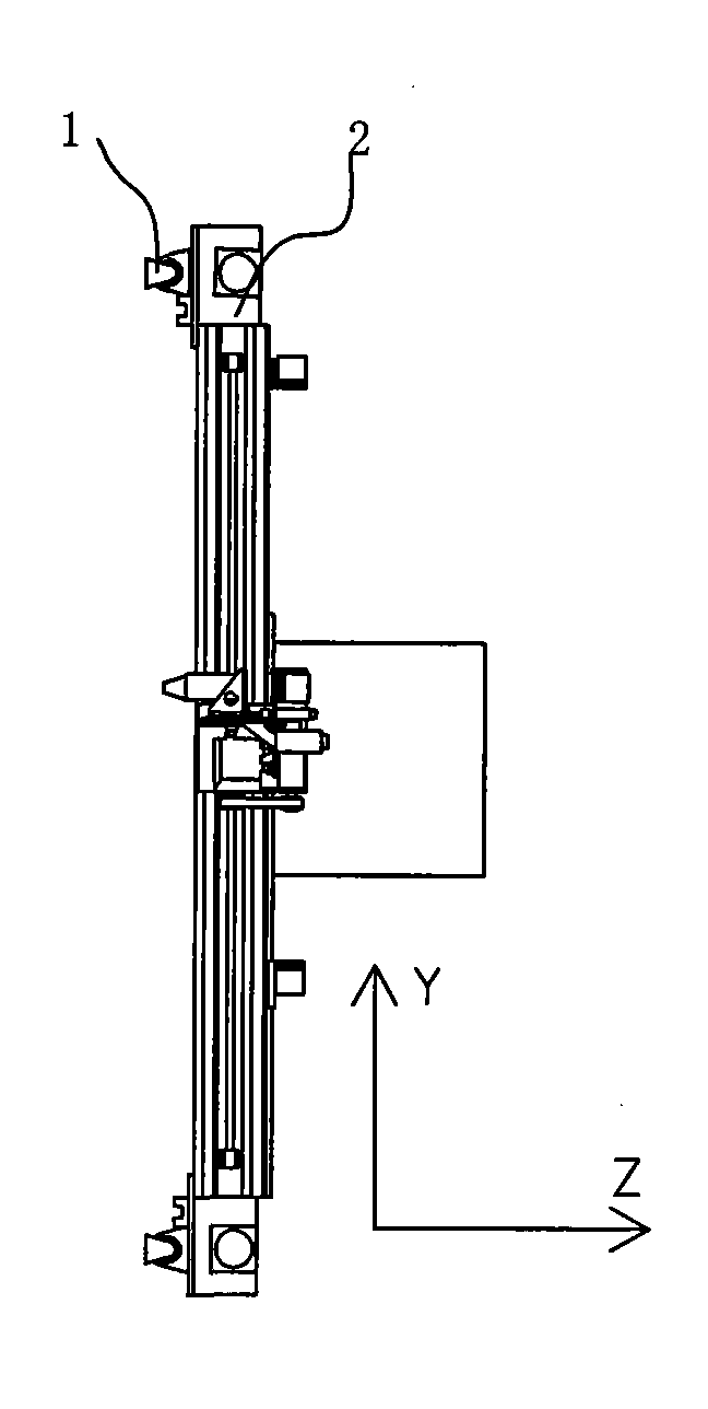
[0034] The present invention is as Figure 1-3 As shown, the cutting machine includes a machine base provided with an X guide rail 1 (which can be a lead screw), a main beam 2 provided with a Y guide rail 4 and a laser head base 7, the laser generator 3 is arranged on the main beam 2, and the laser The head 9 is arranged on the laser head base 7 through the Z-direction guide rail, the main beam 2 is movably connected with the X guide rail 1 on the machine base, and it also includes a cantilever beam 8 for the laser head 9 to realize short-range action in the X-direction; The cantilever beam 8 is provided with an X short guide rail 6; the root of the cantilever beam 8 is movably connected to the Y guide rail 4 on the main beam 2, so that the cantilever beam 8 can move in the Y direction; the laser head seat 7 is movably connected to the X short guide rail 6, and realizes relative movement through the laser head seat driving mechanism 5.

[0035] It also includes a controller, ...


PUM


Abstract

The invention relates to a laser cutting machine and a working method thereof. Like a small-breadth laser cutting machine, the laser cutting machine of the invention has high cutting quality, high efficiency and high accuracy, and the consumed power of a driving system in the cutting process is smaller. The laser cutting machine comprises a stand provided with an X lead rail, a main beam provided with a Y lead rail and a laser head seat, wherein the main beam is movably connected with the X lead rail on the stand; the laser cutting machine also comprises a cantilever beam for a laser head to realize short-distance movement in the X direction; the cantilever beam is provided with an X short lead rail; the root of the cantilever beam is movably connected with the Y lead rail on the main beam to enable the cantilever beam to make Y-direction movement; and the laser head seat is movably connected with the X short lead rail. The working method comprises the following steps: 1. installing a buffer area on the short lead rail; 2. according to different processing requirements, calculating by different steps respectively; and 3. starting the laser cutting machine according to the calculating to manufacture. In the invention, a vector control principle is adopted to synthetize VX minor-axis speed, VX long-axis speed and VY speed so as to effectively control the speed in processing to ensure the processing quality.

Description

technical field [0001] The invention relates to a laser cutting machine and a working method thereof, in particular to an improvement of a heavy-duty large-format thick plate laser cutting machine and a working method thereof. Background technique [0002] Wide and large-format laser cutting machines have great market application prospects. Because of their large cutting widths, the weight of moving parts is usually large. For example, the weight of the main beam alone is 2-3 tons, plus laser generators, water coolers, etc. , about 4-5 tons in weight. The main disadvantages of the large weight of the main beam are: 1. The large weight and inertia make the dynamic response speed of the main beam movement poor, which has a great impact on the machining accuracy and quality. 2. The rigidity of the main beam structure is poor, which will cause a large positioning error of the transmission system. The above two problems make the existing equipment have low precision, low qualit...

Claims


Application Information

Patent Timeline
IPC IPC(8): B23K26/36B23K26/08B23K26/42B23K26/38
Inventor 胡金龙周鹏飞潘志华翟东升洪超
Owner 扬州蝶湖科技产业发展有限公司
Learn More