Encapsulation method of MEMS infrared sensor with infrared focusing function

An infrared sensor and packaging method technology, which is applied to instruments, decorative arts, measuring devices, etc., can solve the problems of infrared heat loss, reduce the sensitivity of infrared detectors, etc. Effect

Inactive Publication Date: 2010-10-20
SOUTHEAST UNIV
View PDF3 Cites 14 Cited by
  • Summary
  • Abstract
  • Description
  • Claims
  • Application Information

AI Technical Summary

Problems solved by technology

[0003] Thermal infrared image sensors generally work at room temperature. If the die that detects infrared rays is in contact with the surrounding air, due to the effect of heat conduction in the air, a large amount of heat generated by infrared rays will be lost, which reduces the performance of the infrared detector. sensitivity

Method used


Image

  • Encapsulation method of MEMS infrared sensor with infrared focusing function
  • Encapsulation method of MEMS infrared sensor with infrared focusing function
  • Encapsulation method of MEMS infrared sensor with infrared focusing function

Examples


Embodiment 1

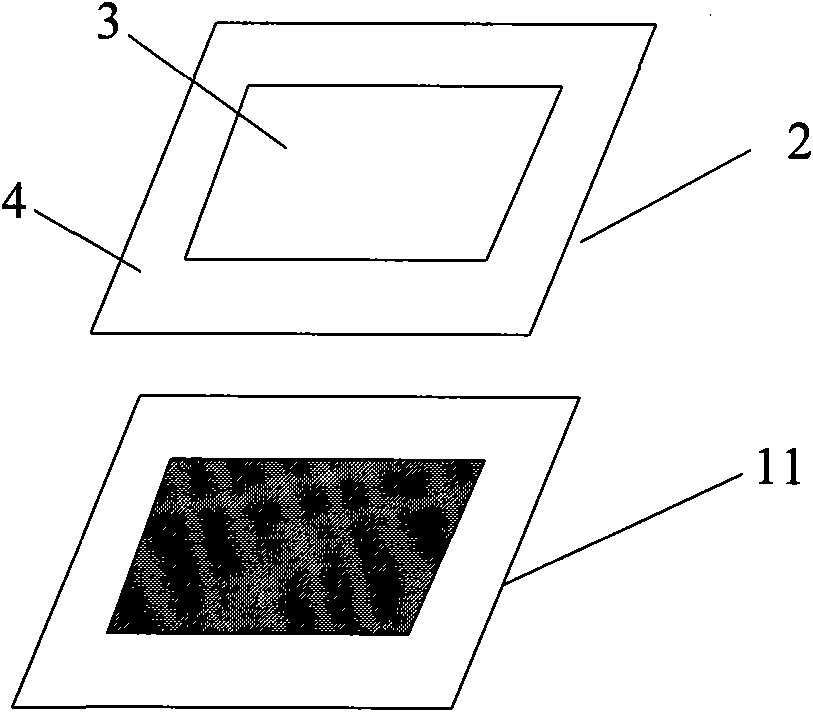
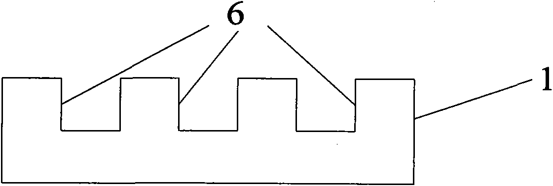
[0033] Embodiment 1 A kind of packaging method of MEMS infrared sensor with infrared focusing function, comprises the following steps: the first step, according to MEMS infrared sensor (can select infrared thermopile for use, it utilizes the variation of the thermocouple measurement temperature of multiple groups connected in series, One end of the thermocouple is connected to the infrared absorption area. Since the temperature rises after absorbing infrared rays, the thermocouple generates a temperature difference. According to the Seebeck effect, the thermopile outputs a voltage. The higher the temperature, the more infrared rays are absorbed, the greater the output voltage value, and the realization In order to detect infrared rays, n-type polysilicon / aluminum thermocouples are used here. For example, the chip size is 1*1 mm), and the pattern and size of the package cavity are determined, including the side length of the cavity and the size of the package area. width, design...

Embodiment 2

[0041] Embodiment 2 A wafer-level packaging method for a MEMS infrared sensor, comprising the following steps:

[0042] The first step is to determine the size of the packaging cavity and the packaging frame according to the structure of the MEMS infrared sensor chip, and design the layout size of the packaging glass microcavity. The MEMS infrared sensor uses multiple sets of thermocouples connected in series to measure the temperature. According to the Seebeck effect, when there is a temperature difference between the two ends of the thermocouple, a voltage will be generated, and the greater the temperature difference between the hot and cold ends, the greater the output voltage. Multiple sets of thermocouples connected in series can improve the detection sensitivity of the thermopile. The hot end of the thermopile is in contact with the infrared absorption area, and the cold end is away from the infrared absorption area, and is insulated with a heat-insulating material, so t...


PUM


Abstract

The invention discloses an encapsulation method of an infrared sensor with infrared focusing function, comprising the following steps: determining the pattern and size of an encapsulated structure according to the infrared sensor chips to be encapsulated, and etching on the silicon wafer to form a specific microgroove pattern conforming to the above encapsulating requirement; bonding the above silicon wafer and a glass wafer to enable the glass wafer and the above specific pattern to form a sealed cavity; heating and insulating the wafer; enabling the softened glass to bulge towards the sealed cavity under the pressure difference of internal and external cavities to form a sphere microcavity structure; cooling; annealing to eliminate stress; utilizing an aligner to align the glass microcavity wafer with infrared sensor chips; and then carrying out secondary anodic bonding in vacuum environment to realize vacuum encapsulation of the infrared sensor, etching a silicon mould, and exposing the lens. The encapsulation method has simple process and low cost, thus not only realizing vacuum encapsulation of the infrared sensor, but also playing the role of focusing to infrared rays and improving detection sensitivity.

Description

technical field [0001] The invention relates to a MEMS (micro-electro-mechanical system) packaging technology, in particular to a packaging method for a MEMS infrared detector with an infrared focusing function. Background technique [0002] With the continuous development of semiconductor industry and MEMS (micro-electro-mechanical system) technology, the manufacturing technology of infrared sensors is also improving day by day. Infrared sensors with superior performance can be manufactured using advanced MEMS micromachining technology. Today, infrared sensors are used more and more widely, such as non-contact rapid measurement of body temperature in medicine, which is of great significance in the need to measure the temperature of a large number of people; in addition, it is also used in scientific research and military, such as Infrared spectrometer, missile guidance, thermal imaging, laser detection and other purposes. In terms of civil and commercial use, infrared sen...

Claims


Application Information

Patent Timeline
Patent Type & Authority Applications(China)
IPC IPC(8): B81C1/00G01J5/00
Inventor 黄庆安尚金堂柳俊文唐洁影徐超张迪陈波寅
Owner SOUTHEAST UNIV
Why Eureka
Try Eureka