Circulating fluidized bed boiler

A circulating fluidized bed and boiler technology, applied in the field of boilers, can solve the problems of high utilization rate of oxygen-enriched combustion heat, huge manufacturing equipment, and no environmental protection effect, and achieve the effect of solving low combustion heat utilization rate

Inactive Publication Date: 2012-05-30
广东中拓能源科技有限公司
View PDF0 Cites 0 Cited by
  • Summary
  • Abstract
  • Description
  • Claims
  • Application Information

AI Technical Summary

Problems solved by technology

[0002] There are currently three mature and advanced combustion technologies for coal-fired boilers in China, namely, coal-water slurry technology, oxygen-enriched combustion technology, and water-gas manufacturing combustion technology. The application effects of these three technologies in actual operation are very ideal. The disadvantage is that the manufacturing equipment is huge and complex, and the capital investment is large
[0008] However, the existing circulating fluidized boilers also have certain defects: 1. The thermal efficiency of the boiler is low; since a large part of the heat of the boiler is taken away by a large amount of air distribution, although the combustion rate of coal is high, it is not rich. Oxygen combustion has a high heat utilization rate, so the thermal efficiency of circulating fluidized bed boilers is low; 2. The environmental protection effect is not as good as that of coal water slurry; due to the influence of air coefficient, the carbon monoxide produced after coal combustion and the Residual carbon, too late to be further burned and exhausted with the tail gas, one is to take away part of the heat, and the other is carbon monoxide and residual carbon itself can be further burned to release heat, resulting in waste of energy. The sulfur and carbon monoxide in the exhaust emissions , There are more soot particles, so the effect of desulfurization and nitrogen oxide removal is not as good as that of coal water slurry, which pollutes the environment

Method used


Image

  • Circulating fluidized bed boiler
  • Circulating fluidized bed boiler

Examples


Embodiment Construction

[0017] The present invention will be further described below in conjunction with the accompanying drawings.

[0018] The following descriptions are only preferred embodiments of the present invention, and therefore do not limit the protection scope of the present invention.

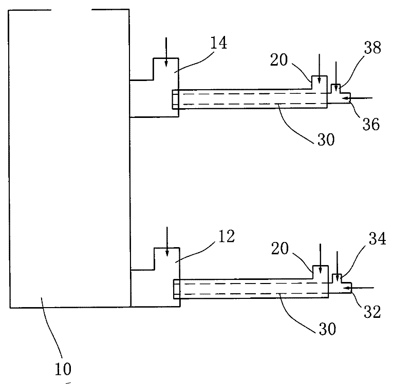
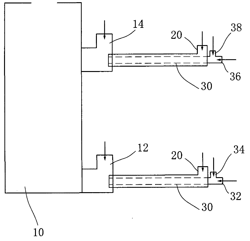
[0019] See attached figure 1 , the present invention includes: boiler 10, boiler 10 has primary air inlet 12 and secondary air inlet 14, because the present invention is to transform existing circulating fluidized bed boiler, therefore, boiler 10 is circulating fluidized bed boiler, once The structure of the air inlet 12 and the secondary air inlet 14 is the same as that of the existing circulating fluidized bed boiler, and will not be described in detail here; the primary air inlet 12 and the secondary air inlet 14 are all equipped with humidification and oxygenation devices. Oxygen device comprises hydrogen peroxide channel 20, steam channel 30, and hydrogen peroxide channel 20, steam channel 30 are al...


PUM


Abstract

The invention relates to the technical field of boilers, in particular to a circulating fluidized bed boiler, which comprises a boiler, wherein the boiler is provided with a primary air inlet and a secondary air inlet, both the primary air inlet and the secondary air inlet are provided with a humidifying and oxygen supplying device, the humidifying and oxygen supplying device comprises a peroxide passage and a steam passage which are communicated with the air inlet. The invention can provide rich-oxygen water steam in the boiler environment to build the necessary conditions for generating rich-oxygen water gas, the tasks of humidification, oxygen supply and the like in site are continuously and stably completed in real time, the rich-oxygen hot water steam environment is created for the combustion of the circulating fluidized boiler, the superior integral conditions of the water-coal-slurry combustion, rich-oxygen combustion and water gas combustion not possessed by the circulating fluidized bed boiler are created, so the heat efficiency of the boiler is improved above the value, and the environment protection effect is obvious.

Description

Technical field: [0001] The invention relates to the technical field of boilers, in particular to circulating fluidized bed boilers. Background technique: [0002] There are currently three mature and advanced combustion technologies for coal-fired boilers in China, namely, coal-water slurry technology, oxygen-enriched combustion technology, and water-gas manufacturing combustion technology. The application effects of these three technologies in actual operation are very ideal. The disadvantage is that the manufacturing equipment is huge and complex, and the capital investment is large. [0003] The application of coal-water slurry technology can replace petroleum and make coal combustion meet environmental protection requirements. It has been recognized by the country and enterprises. Investment, all make enterprises flinch. Since 30% of the water in the coal-water slurry absorbs heat before coal gasification, it has an effect on the combustion process of the coal-water s...

Claims


Application Information

Patent Timeline
Patent Type & Authority Patents(China)
IPC IPC(8): F23C10/00F23L7/00
CPCY02E20/34
Inventor 梁耀权
Owner 广东中拓能源科技有限公司
Why Eureka
Try Eureka