
Formation method of zero object

A technology of zero mark and graphics, applied in the field of zero mark formation, can solve the problems of cumbersome forming process, etc., and achieve the effect of accelerating oxidation rate, saving cycle and manufacturing cost

Active Publication Date: 2010-10-20
SHANGHAI HUAHONG GRACE SEMICON MFG CORP
View PDF0 Cites 1 Cited by
  • Summary
  • Abstract
  • Description
  • Claims
  • Application Information

AI Technical Summary

Problems solved by technology

The above-mentioned formation process is relatively cumbersome, requiring a two-step photolithography process and two photolithography masks

Method used


Image

  • Formation method of zero object
  • Formation method of zero object
  • Formation method of zero object

Examples


Embodiment Construction

[0014] The method for forming the zero mark of the present invention is used in an epitaxial process including a buried layer pattern, comprising the following steps:

[0015] 1) The surface of the substrate is oxidized to form a pad oxide layer;

[0016] 2) Define the positions of the buried layer pattern and the zero mark pattern on the substrate 1 (generally silicon) with a photolithography mask that includes both the buried layer pattern and the zero mark pattern and the photolithography process;

[0017] 3) using the photoresist 2 formed in the photolithography process as a mask to perform buried layer ion implantation to form ion implantation regions at the buried layer pattern position 3 and the zero mark pattern position respectively;

[0018] 4) Common process to remove photoresist and pad oxide layer (see Figure 2a and Figure 2b );

[0019] 5) Afterwards, heat treatment is carried out in an oxygen-containing atmosphere to oxidize the surface of the substrate, an...


PUM


Abstract

The invention discloses a formation method of a zero object, which is used for the epitaxial technology containing a buried layer graph. The formation method comprises the following steps: 1) oxidizing and forming a cushion oxide layer on the surface of a substrate; 2) defining the position of the buried layer graph and the zero scale graph on the substrate by a photoetching mask simultaneously containing the buried layer graph and the zero scale graph and the photoetching technology; 3) taking photoresist formed by the photoetching technology as the mask, carrying out ion implantation, and respectively forming the buried layer and the ion implantation area on the buried layer graph position and the zero scale graph position; 4) removing the photoresist and the cushion oxide layer by common technology; 5) carrying out heat treatment under oxygen-rich environment to oxidize the surface of the substrate, and boosting the buried layer; and 6) removing the oxide layer formed on the surface of the substrate in step 5) with the wet method to obtain the structure with the zero object graph and the buried layer graph. The method of the invention simplifies the formation technology of the zero object.

Description

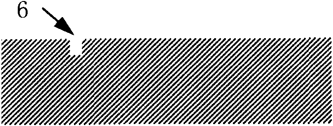
technical field [0001] The invention relates to a method for forming a zero mark, in particular to a method for forming a zero mark in an epitaxy process including buried layer patterns. Background technique [0002] The buried layer is usually used in the epitaxial process to reduce the contact resistance, and the zero mark is the pattern formed on the silicon wafer for the first time, which is used for the next photolithographic alignment. For the epitaxial process with buried layer pattern, the formation of zero mark is usually before the formation of buried layer pattern. A specific example can be found in Figure 1a to Figure 1e : A silicon oxide substrate forms a pad oxide layer on its surface, defines a zero mark pattern with a photoresist on the silicon substrate 1 through a photolithography process, and then uses the photoresist 2 as a mask to etch the silicon substrate to form a zero mark Mark 6, and then remove the photoresist 2; then use another photolithography...

Claims


Application Information

Patent Timeline
Patent Type & Authority Applications(China)
IPC IPC(8): G03F9/00H01L21/00
Inventor 缪燕
Owner SHANGHAI HUAHONG GRACE SEMICON MFG CORP
Learn More