Aluminium conductor terminal device and manufacturing method thereof
A terminal device, aluminum conductor technology, used in the manufacture of contacts, circuit/collector parts, electrical components, etc., can solve the problems of insufficient fusion, low resistance, difficult to have contacts, etc., and achieve high mechanical strength and low resistance. Effect
- Summary
- Abstract
- Description
- Claims
- Application Information
AI Technical Summary
Problems solved by technology
Method used
Image

Examples
no. 1 approach
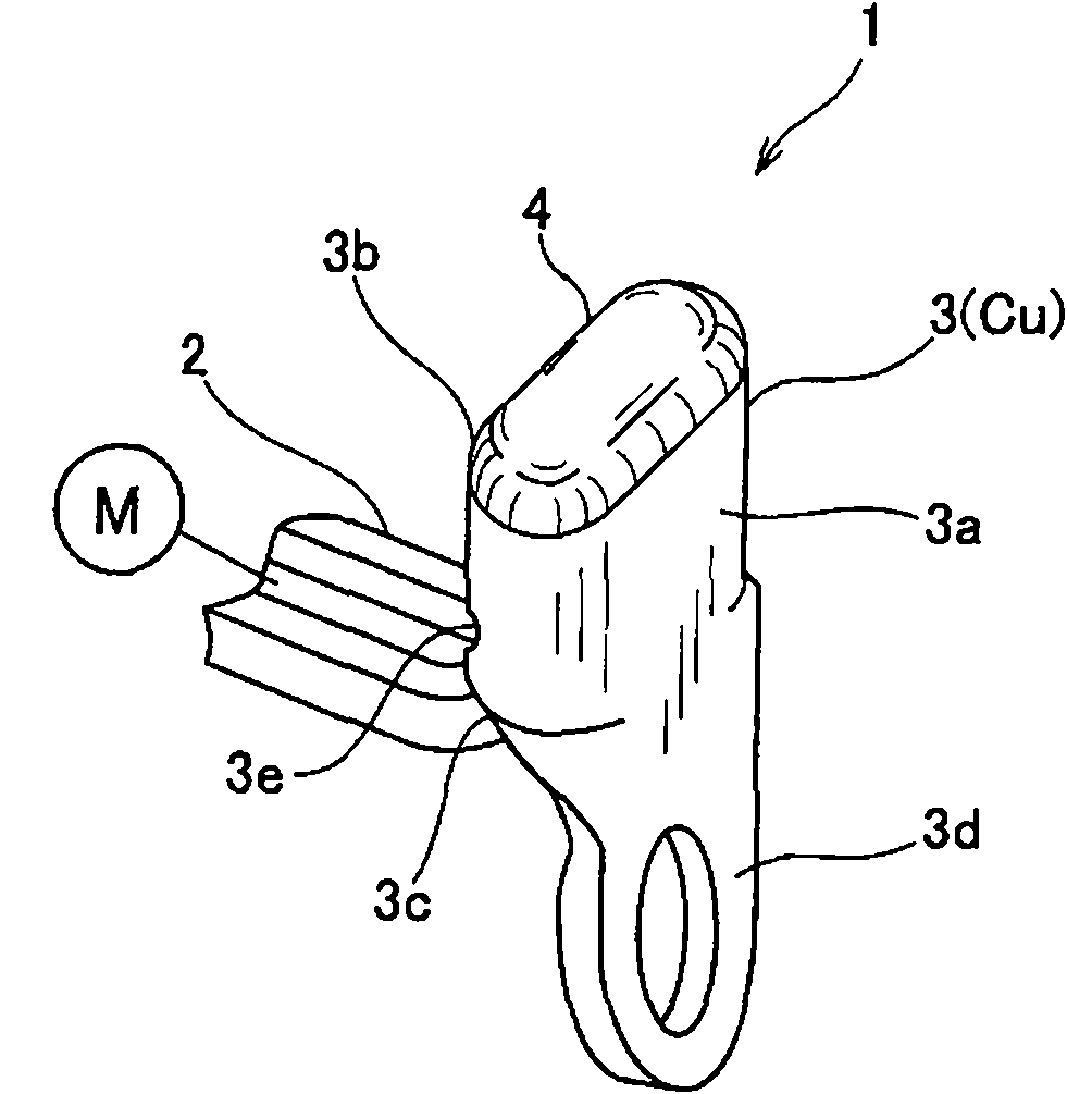
[0033] figure 1 is a perspective view of an aluminum conductor terminal device 1 according to a first embodiment of the present invention.
[0034] The terminal device 1 is a contact connection type terminal used for connection of a power supply line of electric equipment such as a rotating electric machine. For example, the terminal arrangement 1 may be used to provide electrical connections in the stator coils of an on-vehicle rotating electrical machine. In this case, the terminal arrangement 1 is used to connect a plurality of phase windings of the stator coil. A plurality of phase windings are soldered and connected to each other by means of the terminal device 1 .
[0035] Furthermore, the terminal arrangement 1 can be used to connect multiple phase windings to an electrical circuit. To this end, the terminal arrangement 1 comprises pole parts to which the electric circuit is contact-connected to provide an electrical connection between the phase windings and the elec...
no. 2 approach
[0067] Next, a second embodiment of the present invention will be described. In the following embodiments, the same parts as those shown in the preceding figures are given the same reference numerals and will not be described again unless necessary for understanding the embodiments. Figure 8 is a perspective view of an aluminum conductor terminal device of a second embodiment. Such as Figure 8 As shown, the aluminum conductor terminal device 1 of the second embodiment includes a terminal member 23 having an electrode portion 23d. The electrode portion 23d is bent at 90 degrees with respect to the axial direction of the tubular portion 3a. The electrode portion 23d extends in a direction opposite to the direction in which the aluminum conductor 2 extends. The flat portion of the electrode portion 23d expands perpendicularly to the axis of the tubular portion 3a.
no. 3 approach
[0069] Next, a third embodiment of the present invention will be described. Figure 9 is a perspective view of an aluminum conductor terminal device of a third embodiment. Such as Figure 9 As shown, the aluminum conductor terminal device 1 of the third embodiment includes a terminal member 33 having an electrode portion 33d. The electrode portion 33d is bent at 90 degrees with respect to the axial direction of the tubular portion 3a, and is twisted at 90 degrees. The electrode portion 33d extends in a direction opposite to the direction in which the aluminum conductor 2 extends. The flat portion of the electrode portion 33d expands perpendicularly to the axis of the tubular portion 3a.
PUM
 Abstract
Description
Claims
Application Information
 - Generate Ideas
- Intellectual Property
- Life Sciences
- Materials
- Tech Scout
- Unparalleled Data Quality
- Higher Quality Content
- 60% Fewer Hallucinations
Browse by: Latest US Patents, China's latest patents, Technical Efficacy Thesaurus, Application Domain, Technology Topic, Popular Technical Reports.
© 2025 PatSnap. All rights reserved.Legal|Privacy policy|Modern Slavery Act Transparency Statement|Sitemap|About US| Contact US: help@patsnap.com