Charging circuit and charger

A charging circuit and charger technology, applied in the circuit field, can solve problems such as battery damage

Inactive Publication Date: 2010-10-20
SHENZHEN RUIBIDA TECH
View PDF4 Cites 30 Cited by
  • Summary
  • Abstract
  • Description
  • Claims
  • Application Information

AI Technical Summary

Problems solved by technology

[0003] The purpose of the embodiment of the present invention is to provide a charging circuit, aiming to solve the problem of serious damage to the charger and the battery when the polarity of the battery is reversed

Method used


Image

  • Charging circuit and charger
  • Charging circuit and charger
  • Charging circuit and charger

Examples


Embodiment 1

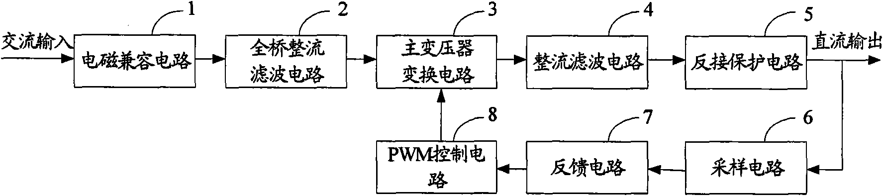
[0057] figure 1 The circuit structure of the charging circuit provided by the embodiment of the present invention is shown. For convenience of description, only the part related to the embodiment of the present invention is shown.

[0058] The electromagnetic compatibility circuit 1 performs high-frequency filtering on the AC input to eliminate high-frequency interference.

[0059] The full-bridge rectifying and filtering circuit 2 rectifies the alternating current output by the electromagnetic compatibility circuit 1 into a pulsating direct current, and filters the output to the main transformer conversion circuit 3 .

[0060] The main transformer conversion circuit 3 receives the output current of the full-bridge rectifier and filter circuit 2 and the PWM control signal output by the PWM control circuit 8, adjusts the strength of energy storage and discharge according to the PWM control signal, and outputs the current.

[0061] The rectifying and filtering circuit 4 receive...

Embodiment 2

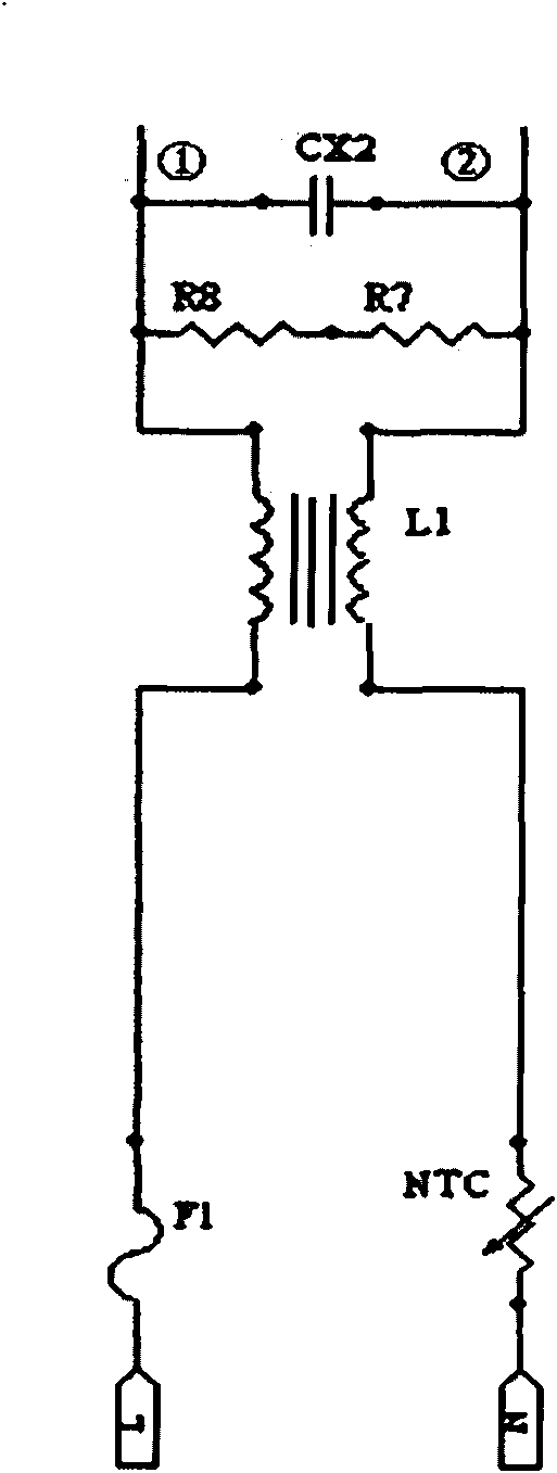
[0068] figure 2 The structure of the electromagnetic compatibility circuit provided by the embodiment of the present invention is shown. For convenience of description, only the part related to the embodiment of the present invention is shown.

[0069] The electromagnetic compatibility circuit 1 includes a fuse F1, an anti-lightning varistor NTC, a common mode inductor L1, resistors R7, R8 and a differential mode capacitor CX2.

[0070] The AC input L terminal is connected with a fuse F1, the AC input N terminal is connected with a lightning protection varistor NTC, and the common mode inductor L1 includes a first winding and a second winding.

[0071] The other end of the fuse F1 is connected to the first winding of the common mode inductor L1, and the other end of the first winding of the common mode inductor L1 is defined as ①.

[0072] The other end of the lightning protection varistor NTC is connected to the second winding of the common mode inductor L1, and the other e...

Embodiment 3

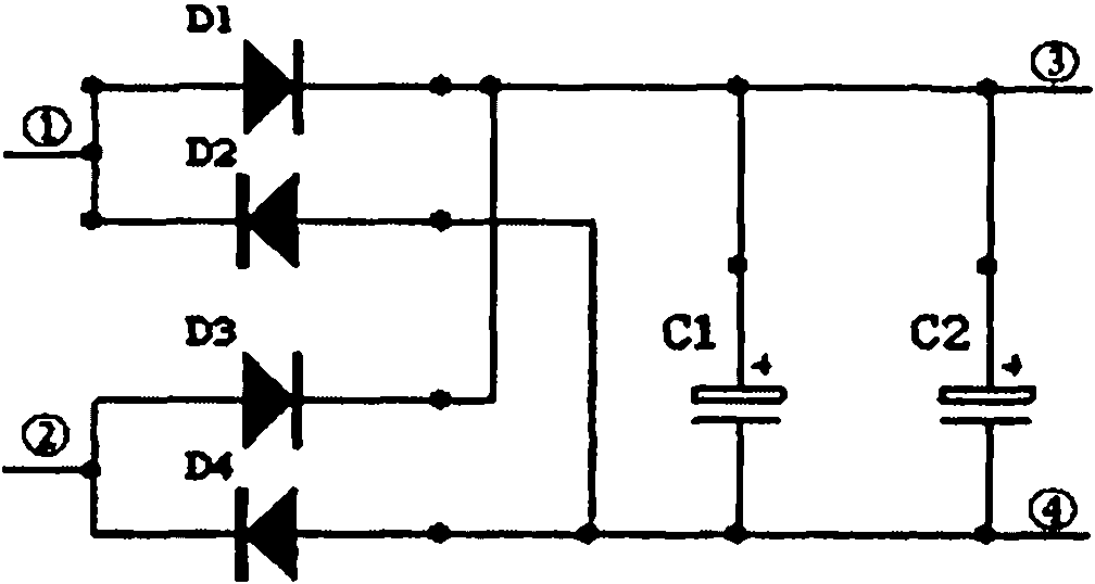
[0077] image 3 The structure of the full-bridge rectification filter circuit provided by the embodiment of the present invention is shown. For convenience of description, only the part related to the embodiment of the present invention is shown.

[0078] The full-bridge rectification filter circuit includes diodes D1, D2, D3, D4 and electrolytic capacitors C1, C2.

[0079] Diodes D1, D2, D3, and D4 form a full-bridge rectifier. The anode of diode D1 is connected to the cathode of diode D2, and the cathode of diode D1 is connected to the cathode of diode D3.

[0080] The anode of diode D3 is connected to the cathode of diode D4, and the anode of diode D4 is connected to the anode of diode D2.

[0081] The heteropolar contacts of the diodes D1 and D2 are connected to the output ① of the electromagnetic compatibility circuit 1 , and the heteropolar contacts of the diodes D3 and D4 are connected to the output ② of the electromagnetic compatibility circuit 1 .

[0082] The anode...


PUM


Abstract

The invention, which is applicable to the field of circuits, provides a charging circuit and a charger. The circuit comprises an electromagnetic compatibility circuit, a full-bridge rectifier and filter circuit, a main transformer transformation circuit, a rectifier and filter circuit, a reverse connection protection circuit, a sampling circuit, a feedback circuit and a PWM control circuit; the electromagnetic compatibility circuit is used for carrying out the high-frequency filtering of alternating-current input; the full-bridge rectifier and filter circuit is used for rectifying alternatingcurrent into pulsating direct current; the main transformer transformation circuit is used for storing and releasing electric energy according to PWM control signals; the rectifier and filter circuitis used for rectifying, filtering and outputting current; the reverse connection protection circuit is used for receiving regulated current and shutting off the charging circuit when the poles of a battery are reversely connected; the sampling circuit is used for acquiring voltage signal output; the feedback circuit is used for comparing the voltage signal with the reference voltage and then outputting a feedback signal; and the PWM control circuit is used for receiving the feedback signal and outputting a PWM control signal. By shutting off the charging circuit when the poles of the battery are reversely connected, the invention prevents the damage of the charger and the battery when the chargeable battery is reversely connected.

Description

technical field [0001] The invention belongs to the field of circuits, and in particular relates to a charging circuit and a charger. Background technique [0002] In recent years, with the rapid development of electrical technology, electric vehicles, power tools, notebooks, digital, small portable electronic devices and electronic devices using rechargeable batteries have become increasingly popular, and battery chargers are widely used. Due to the existence of other factors such as user operation, the polarity of the rechargeable battery may be reversed, causing serious damage to the charger and the rechargeable battery, and the leakage current of the battery is too large under long-term storage. Obviously, the use of effective battery charger reverse polarity protection is a priority. SUMMARY OF THE INVENTION [0003] The purpose of the embodiments of the present invention is to provide a charging circuit, which aims to solve the problem of serious damage to the charg...

Claims


Application Information

Patent Timeline
Patent Type & Authority Applications(China)
IPC IPC(8): H02J7/04H02J7/10H02H11/00
Inventor 胡三红杨猛
Owner SHENZHEN RUIBIDA TECH
Why Eureka
Try Eureka