Driving controller of electric eddy current brake and control method thereof

An eddy current retarder and drive controller technology, applied in electric vehicles, electric braking systems, motors, etc., can solve problems such as high failure rate and easy failure, improve reliability, limit temperature rise, and solve reliable problems. low sex effect

Inactive Publication Date: 2010-10-20
深圳市大为创新科技股份有限公司
View PDF6 Cites 16 Cited by
  • Summary
  • Abstract
  • Description
  • Claims
  • Application Information

AI Technical Summary

Problems solved by technology

[0002] Chinese invention patent "Eddy current retarder drive controller and its control method", patent number 200510034403.9, discloses a drive controller for eddy current retarder, which is the same as other traditional eddy current retarder drive controllers. The intelligent power module (BTS550P) of this kind of auxiliary circuit is used as a power device, but its withstand voltage is only 40V, which is very easy to fail, which is the root cause of the high failure rate

Method used


Image

  • Driving controller of electric eddy current brake and control method thereof
  • Driving controller of electric eddy current brake and control method thereof
  • Driving controller of electric eddy current brake and control method thereof

Examples


Embodiment Construction

[0024] The present invention is described in conjunction with specific embodiments of the present invention:

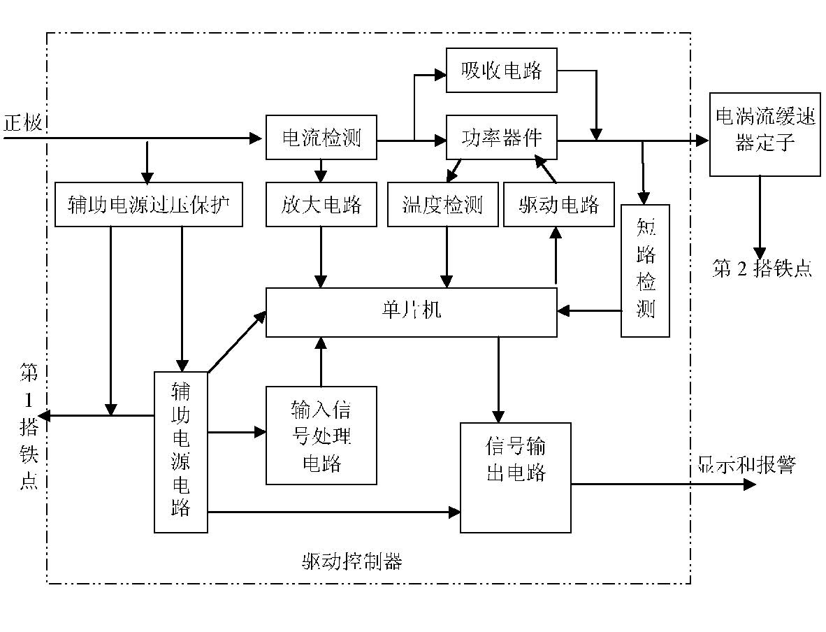
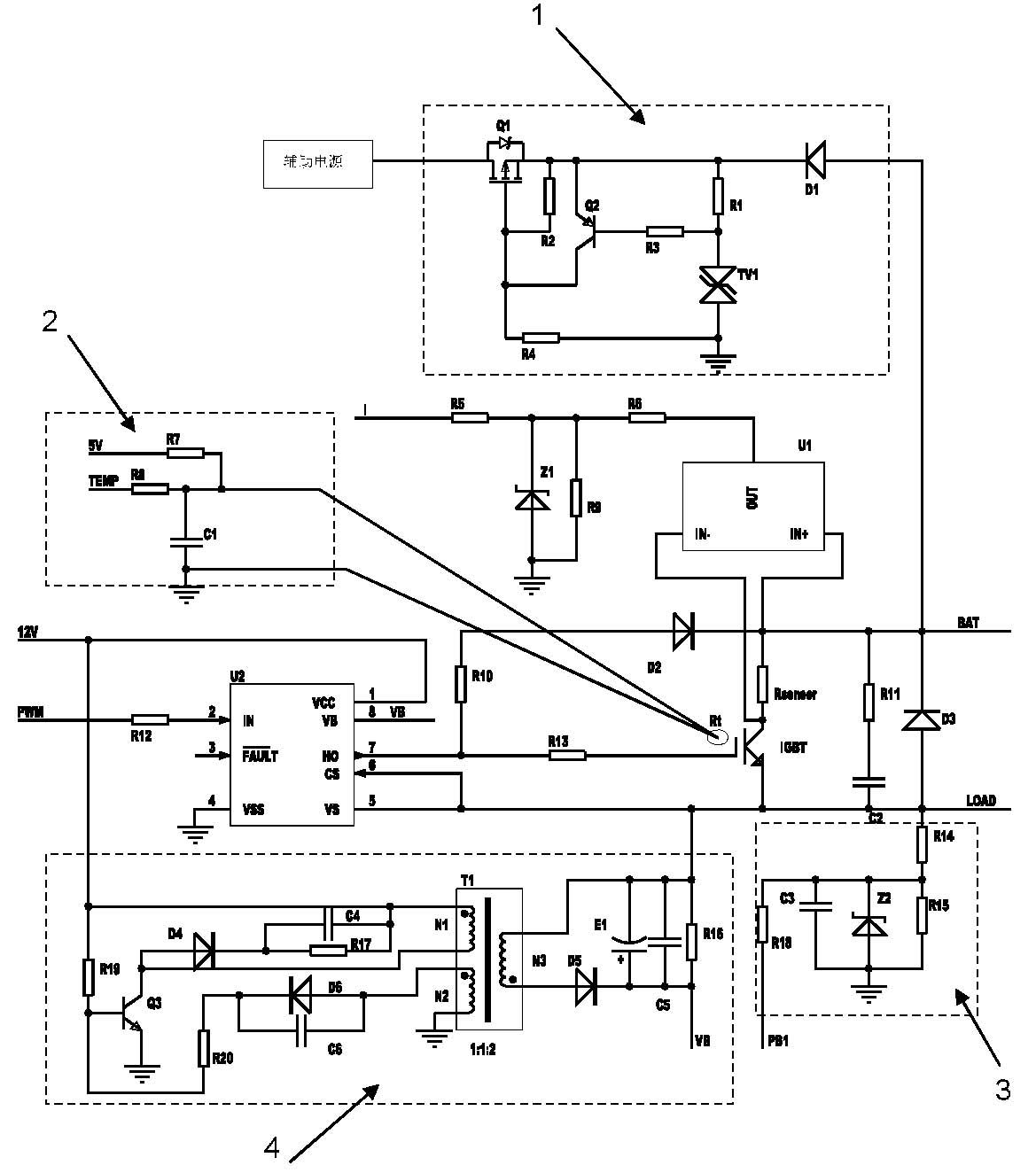
[0025] like figure 1 , as shown in 3, the eddy current retarder drive controller of the present invention includes a single-chip microcomputer, a power device, a power device drive circuit and various auxiliary circuits, including: an overvoltage protection unit 1 of an auxiliary power supply, a temperature detection unit 2, and a short circuit detection unit 3 and the isolated direct current DC power supply 4 in the drive circuit, image 3 Middle I end, PWM end, PB1 end connect described single-chip corresponding port, LOAD end connects load, BAT end connects automobile generator and battery.

[0026] Compared with the traditional eddy current retarder, the innovation of the present invention lies in:

[0027] (1) IGBT and its driving circuit

[0028] Technical problem 1: For the sake of safety, one end of the vehicle-mounted high-current equipment is directly gro...


PUM


Abstract

The invention relates to a driving controller of an electric eddy current brake and a control method thereof, wherein the controller comprises a control unit, a driving circuit and an insulated gate bipolar transistor IGBT with large current and high pressure resistance electrically connected in sequence, and a rectification unit, a transformer T1 and a power input thereof connected with an IGBT output grid electrode in sequence. The control method comprises the steps that the control unit controls the pulse width thereof according to the input gear to modulate the duty ratio of the PWM output under the condition of normal circuit detection, or else turns off the output or restricts the duty ratio of the PWM output; the driving circuit receives the PWM output and drives the IGBT output according to the PWM output. The driving controller of the electric eddy current brake and the control method thereof has the high pressure resistance of 300V, and basically avoids the over-voltage failure used on cars, the controller can not be failed under various abnormal conditions combining a detection and protection circuit, thereby greatly enhancing the reliability, and solving the industrial problem of poor reliability of electronic control mode in the electric eddy current brake industry.

Description

technical field [0001] The invention relates to automobile braking equipment, in particular to an eddy current retarder drive controller and a control method thereof. Background technique [0002] Chinese invention patent "Eddy current retarder drive controller and its control method", patent number 200510034403.9, discloses a drive controller for eddy current retarder, which is the same as other traditional eddy current retarder drive controllers. The intelligent power module (BTS550P) of this auxiliary circuit is used as a power device, but its withstand voltage is only 40V, which is very easy to fail, which is the root cause of the high failure rate. Contents of the invention [0003] The technical problem to be solved in the present invention is how to provide a drive controller and a control method for the eddy current retarder, which can work more stably and effectively. [0004] The first technical problem of the present invention is solved in this way: build a kin...

Claims


Application Information

Patent Timeline
Patent Type & Authority Applications(China)
IPC IPC(8): H02P3/04B60L7/28
CPCY02T10/7241Y02T10/642Y02T10/64Y02T10/72
Inventor 梁勇伍中权
Owner 深圳市大为创新科技股份有限公司
Why Eureka
Try Eureka