Radial artery puncturing and positioning device

A positioning device and radial artery technology, applied in puncture needles, medical science, surgery, etc., can solve the problems of not being able to accurately determine the direction and specific position of the radial artery, and fail to ensure a successful puncture, so as to avoid pain, facilitate operation, reduce workload effect

Inactive Publication Date: 2010-10-27
DALIAN MEDICAL UNIVERSITY
View PDF8 Cites 5 Cited by
  • Summary
  • Abstract
  • Description
  • Claims
  • Application Information

AI Technical Summary

Problems solved by technology

The patented technology is "made of PVC material with an arc-shaped supporting surface at the top". Although the back of the palm is placed on it when puncturing, it can maintain the stability of the palm during d...

Method used


Image

  • Radial artery puncturing and positioning device
  • Radial artery puncturing and positioning device
  • Radial artery puncturing and positioning device

Examples


Embodiment 1

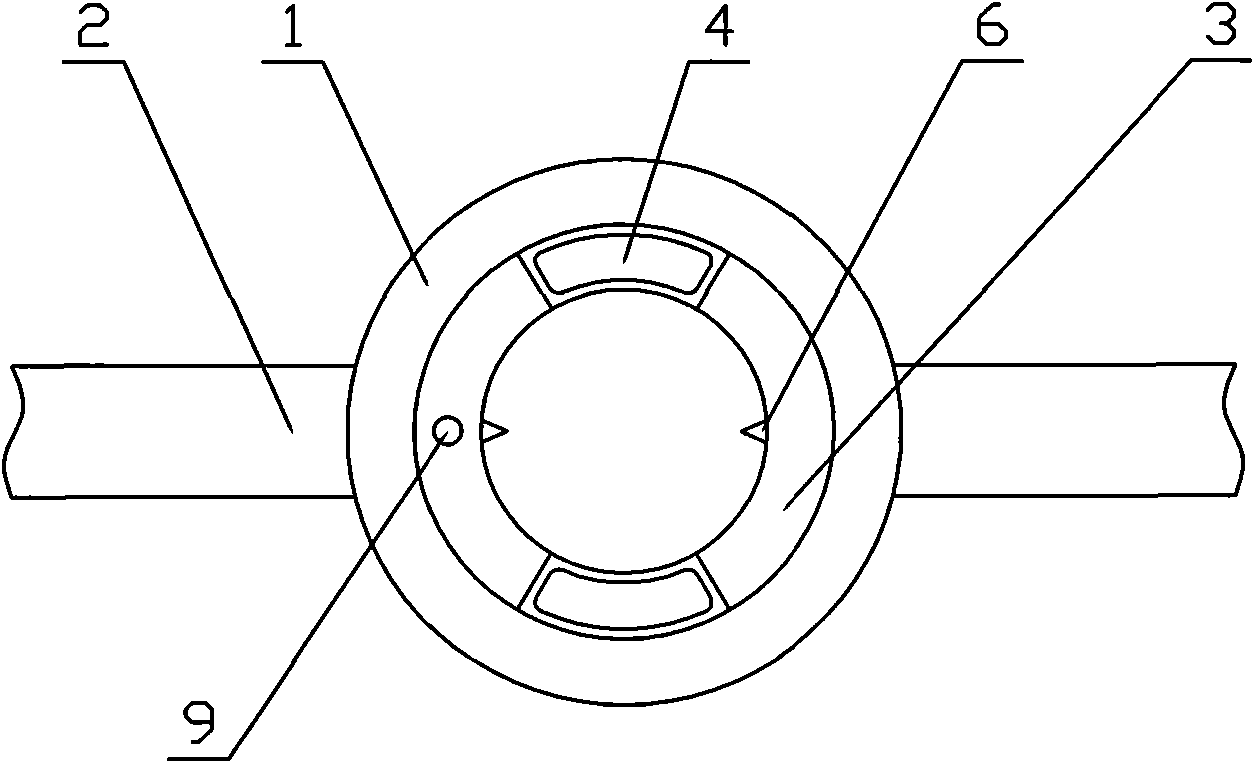
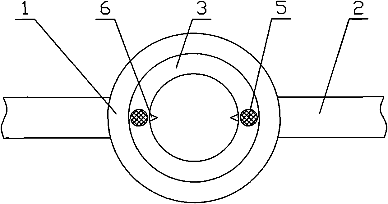
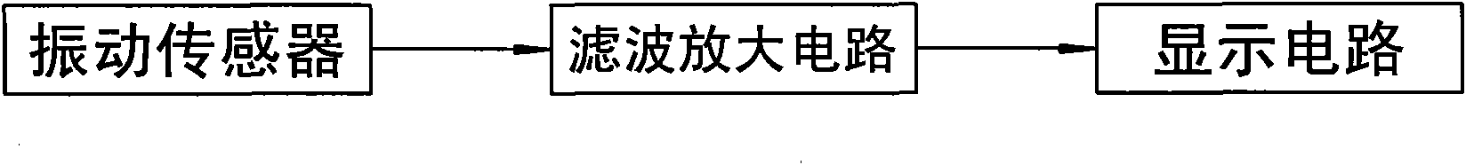
[0011] Example 1 as figure 1 , 2 Shown in , 3: fixed ring 1 is arranged, and like wrist watch, connecting band 2 is connected at fixed ring 1 radial direction both sides, and the end of connecting band 2 has fixing member, as Velcro etc. There is a rotating ring 3 slidingly connected under the fixed ring 1, a pressure display screen 4 is provided on the rotating ring 3, and a vibration sensor 5 is symmetrically arranged on the bottom surface of the rotating ring 3, preferably on both sides in the radial direction. Symmetrical on both sides of the string, but make sure there is enough operating range. The output of the vibration sensor 5 is connected with the pressure value display circuit through the filter amplifier circuit, the filter amplifier circuit can be placed in the rotating ring 3, the display circuit is placed under the display screen 4, two display circuits and the display screen 4 can be set, or two Only one is set, but the pressure values ​​of the two symmetric...

Embodiment 2

[0012] Example 2 as Figure 4 Shown: the basic structure is the same as that of embodiment 1, the difference from embodiment 1 is that the connection belt 2 on one side of the fixing ring 1 is connected to one end of the hemostatic buckle bowl 7, and is located on the connection belt 2 on the other side of the fixing ring 1 A connecting buckle 8 that can be connected with the hemostatic buckle bowl 7 is provided, and the looseness of the hemostatic buckle bowl 7 can also be adjusted except that the connecting buckle 8 can be connected and fixed.

[0013] The operation method is as follows:

[0014] 1. Place Embodiment 2 of the present invention on the wrist and fix it by connecting strap 2;

[0015] 2. Turn on the switch 9, observe the voltage value on the display screen 4, and rotate the rotating ring 3 to make the two voltage values ​​displayed on the display screen reach the maximum, that is, the two symmetrical vibration sensors 5 are placed on the radial artery;

[0016...


PUM


Abstract

The invention discloses a radial artery puncturing and positioning device comprising a fixing ring (1), and two sides of the radial direction of the fixing ring (1) are connected with connecting belts (2); a rotation ring (3) is connected below the fixing ring (1) in a sliding mode and is provided with a pressure numerical value display screen (4); the bottom surface of the rotation ring (3) is symmetrically provided with vibrating sensors (5) of which the output is connected with the pressure numerical value display circuit by a filtering amplifying circuit; and the rotation ring (3) is provided with a para-position identification (6) marking the position of the vibrating sensors (5). The vibration sensing technology is combined with LED screen voltage numerical value display to replace the mode of finger touch in the traditional method, so that the invention can accurately position the running direction and the position of the radial artery, improves first-time success rate of puncture, reduces the work load of arteriopuncture and avoids brining pain to patients by repeated puncture; and after the puncturing, a hemostasis bowl presses to carry out hemostasis, and the invention is convenient and quick to operate.

Description

Technical field: [0001] The invention relates to a radial artery puncture device, in particular to a radial artery puncture positioning device which can realize precise positioning of the direction and position of the radial artery and improve the success rate of one-time puncture. Background technique: [0002] With the development of clinical testing and treatment methods, arterial puncture has become a common clinical operation method, and is widely used in coronary interventional therapy, thrombolytic therapy, and arterial blood sampling. The traditional puncture is completely positioned by the touch of the fingers of the operating medical staff. Since the position of the radial artery changes with the movement of the soft tissue, the puncture needle tends to deviate when it enters, and it is difficult to accurately enter the artery. Sometimes repeated or even multiple punctures are required to succeed. Repeated puncture not only brings great pain to the patient, but als...

Claims


Application Information

Patent Timeline
IPC IPC(8): A61B19/00A61B17/34
Inventor 付元山王滨马晓凯蔡琳唐炜马景馨王茜陈晓燕
Owner DALIAN MEDICAL UNIVERSITY
Why Eureka
Try Eureka