
Eureka
For R&D, Eureka makes reading and utilizing patents & technical documents easy.
Eureka AIR
Designed for self-driven R&D workflows. Generate viable solutions, solve complex R&D challenges, empower your innovation with AI.

Eureka Materials
Designed for material experts only. Revolutionize your material R&D, from search, analyze, to developing new materials.

TechResearch
Generate reliable direction feasibility study reports for your R&D in just a few steps.

TechSeek
Discover and master advanced knowledge NOW. Basics, ideas, possibilities, all at once.

TechMind
As an expert in R&D Theories, TechMind can generates customized viable solutions instantly.

TechRisk
Analyze your overall solution with one click, know your potential R&D risks in advance.

TechMonitor
Get weekly tech updates, stay abreast of the latest tech innovations and key insights.
Ultraviolet fluid radiation system with modular ultraviolet lamps and modular ballasts
A radiation system and ballast technology, applied in the field of ultraviolet fluid radiation systems, can solve the problems of damage to the ultraviolet lamp and its casing, damage to the ultraviolet lamp and the ballast, and uneven weight distribution of the module, so as to avoid the lamp tube and its casing. and its effect of casing breakage, improving system safety, and reducing the risk of breakage
- Summary
- Abstract
- Description
- Claims
- Application Information
AI Technical Summary
Problems solved by technology
Method used
Image

Examples
Embodiment 1
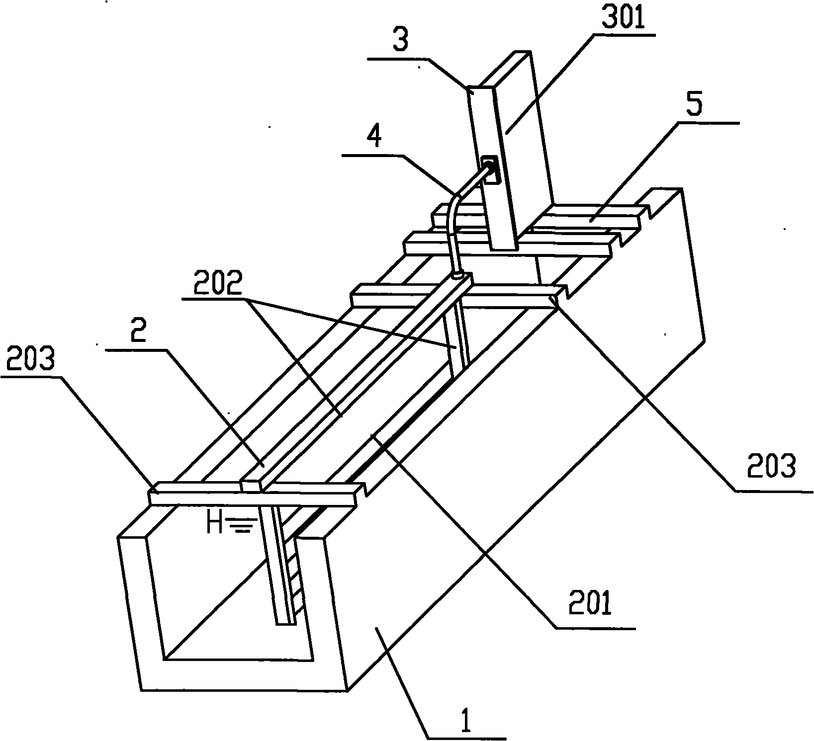
[0029] Such as figure 2 As shown in the figure, it can be clearly seen that the UV lamp module 2 in this embodiment is fixed in the water channel 1 by its mounting frame 203, and the ballast module 3 is fixed by the fixing bracket of the ballast box and its fastening device 5 Above the outside of the UV lamp module mounting frame 203.
[0030] The ultraviolet fluid radiation system adopting the technical scheme of the present invention includes at least one ultraviolet lamp module 2 and a ballast matched with the ultraviolet lamp tube 201 in the ultraviolet lamp module. Each ultraviolet lamp module 2 includes a plurality of ultraviolet lamp tubes 201 and a lamp tube support frame 202. The ballast of the ultraviolet lamp tube also adopts a modular structure. In this embodiment, each ultraviolet lamp module 2 corresponds to a ballast Each ballast module 3 includes a ballast box 301 for encapsulating the ballast and several ballasts (packaged in the box, not shown), the ballast mod...
Embodiment 2
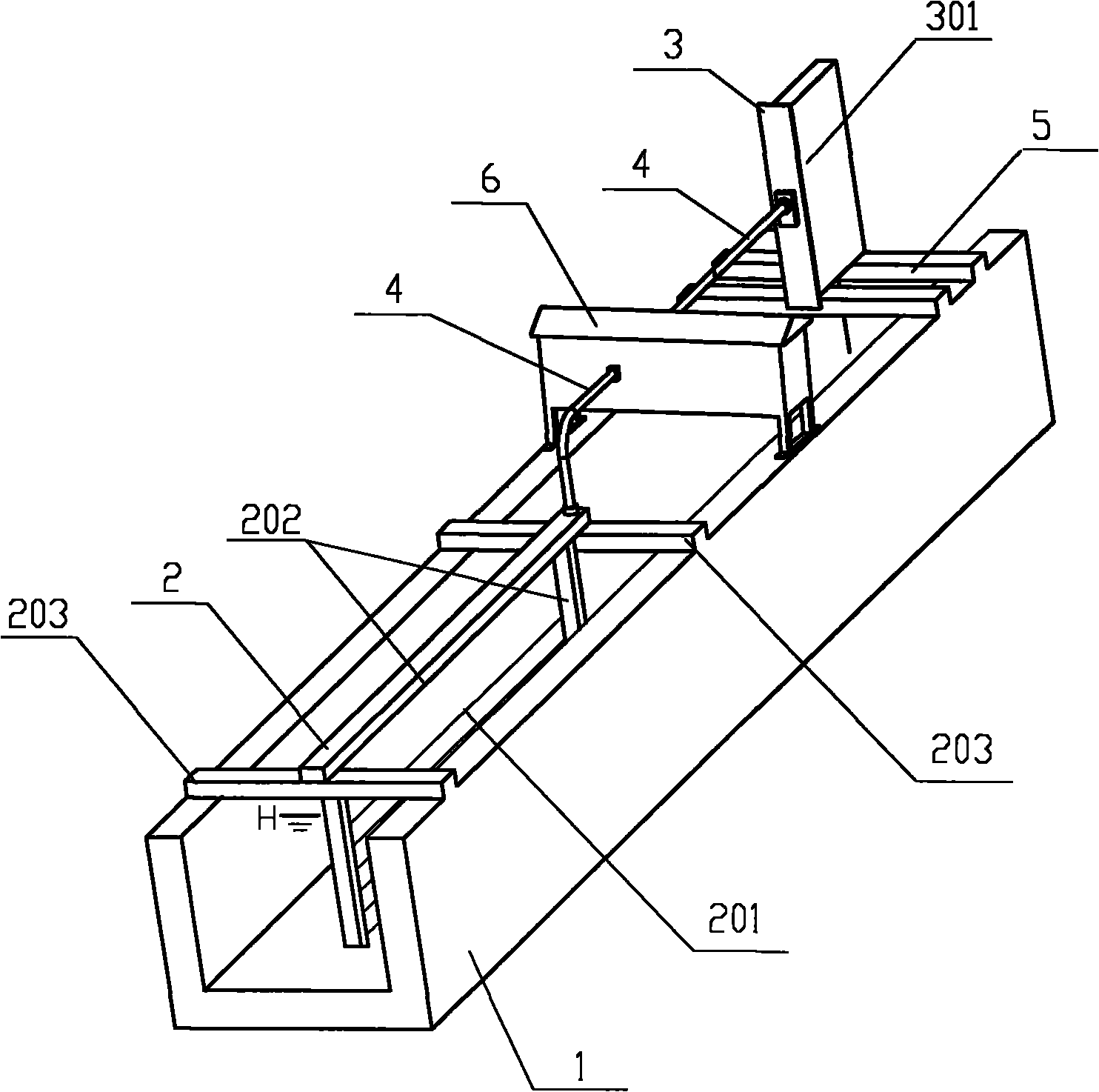
[0032] Such as image 3 As shown in the figure, it can be clearly seen that the UV lamp module 2 in this embodiment is fixed in the water channel 1 by its mounting frame 203, and the ballast module 3 is fixed by the fixing bracket of the ballast box and its fastening device 5 Above the outside of the UV lamp module mounting frame 203.
[0033] The difference from Embodiment 1 is that the ballast module 3 and its corresponding UV lamp module 2 are electrically connected through the electrical connection line 4 and the cross-drain electrical box 6, and there is no connection between the ballast module 3 and the UV lamp module 2. Mechanical connection. The bottom of the ballast box 301 is higher than the liquid level H of the fluid in the channel 1. Each cross-channel electrical box can be connected to at least two ballast modules and its corresponding UV lamp module. In this embodiment, only one ballast module and its corresponding UV lamp module are shown as an illustration.
Embodiment 3
[0035] Such as Figure 4 As shown in the figure, it can be clearly seen that the UV lamp module 2 in this embodiment is fixed in the water channel 1 by its mounting frame 203, and the ballast module 3 is fixed by the fixing bracket of the ballast box and its fastening device 5 Above the outside of the UV lamp module mounting frame 203.
[0036] The difference from the first embodiment is that the multiple UV lamp modules 2 in this embodiment correspond to one ballast module 3, and each ballast module 3 includes a ballast box 301 for encapsulating the ballast and Several ballasts (encapsulated in a box, not shown), the ballast module 3 and the ultraviolet lamp module 2 are directly electrically connected through the electrical connection line 4, and the ballast module 3 and the ultraviolet lamp module 2 are electrically connected No mechanical connection. The bottom of the ballast box 301 is higher than the liquid level H of the fluid in the channel 1. The ultraviolet lamp modu...
PUM
 Abstract
Description
Claims
Application Information
 - R&D Engineer
- R&D Manager
- IP Professional
- Industry Leading Data Capabilities
- Powerful AI technology
- Patent DNA Extraction
Browse by: Latest US Patents, China's latest patents, Technical Efficacy Thesaurus, Application Domain, Technology Topic, Popular Technical Reports.
© 2024 PatSnap. All rights reserved.Legal|Privacy policy|Modern Slavery Act Transparency Statement|Sitemap|About US| Contact US: help@patsnap.com