Laser line light source system with uniform lighting

A technology of laser line light source and uniform lighting, which is applied to the components of lighting devices, lasers, electric light sources, etc., which can solve problems such as uneven exposure of images, and achieve the effect of solving light interference and eliminating clear shooting

Active Publication Date: 2010-10-27
HARBIN KEJIA GENERAL MECHANICAL & ELECTRICAL CO LTD
View PDF0 Cites 7 Cited by
  • Summary
  • Abstract
  • Description
  • Claims
  • Application Information

AI Technical Summary

Problems solved by technology

[0004] The purpose of the present invention is to provide a uniform lighting that can completely solve the problem of uneven exposure of the vehicle body parts image captured by the dynamic image detection system for trucks (passenger cars, EMUs, locomotives) when traditional light sources of scattering or reflective light are used. laser line light source system

Method used


Image

  • Laser line light source system with uniform lighting
  • Laser line light source system with uniform lighting
  • Laser line light source system with uniform lighting

Examples


Embodiment 1

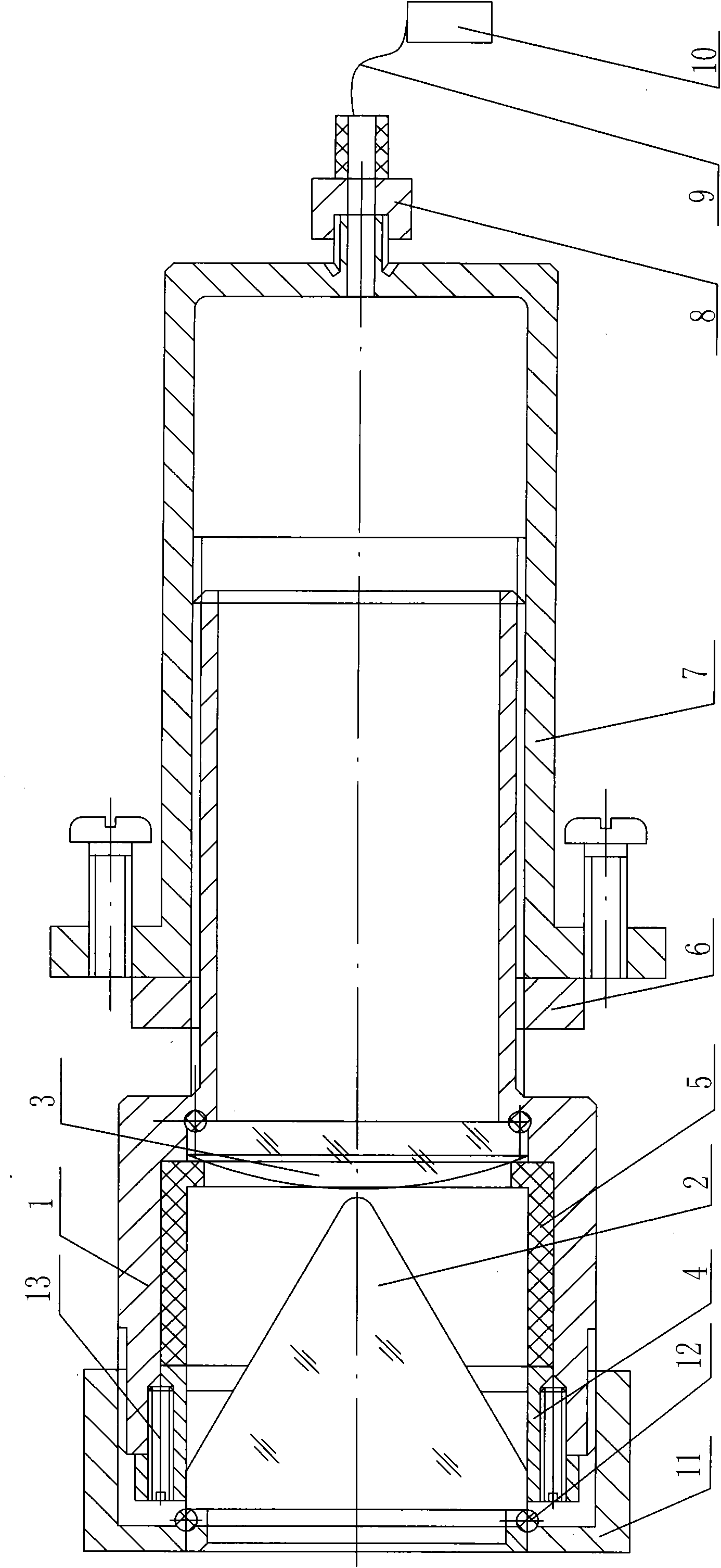
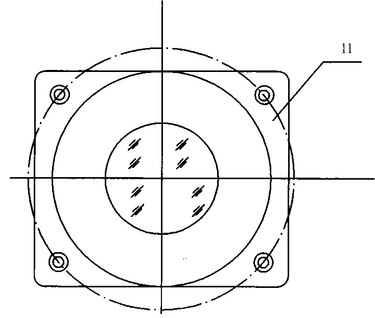
[0026] A uniformly illuminated laser line light source device, which consists of a stepped adjustable focus prism and a lens barrel 1. The position of the large diameter of the adjustable focus prism and lens barrel 1 is equipped with a prism 2 and a convex lens 3. The prism 2 is covered with a prism sheath 4, the prism sheath 4 is connected to the retaining ring 5, the adjustable focus prism, the small diameter position sleeve in the lens barrel 1 is connected to the adjustment nut 6 and the laser lamp body 7, One side of the laser lamp body 7 is connected to an optical fiber connector 8, and the optical fiber connector 8 is connected to a semiconductor laser 10 through an optical fiber 9, and the large-diameter end of the adjustable focus prism and lens barrel 1 is connected to a sealing glass cover 11.

[0027] The laser line light source device for uniform illumination, the other side of the laser lamp body 7 is connected with the adjusting nut 6, the adjustable focus prism...

Embodiment 2

[0030] Uniformly illuminated laser line light source system, the point light source output by the semiconductor laser is exported through direct connection or optical fiber transmission and then connected to the optical lens system. To the surface of the object to be photographed to achieve efficient and uniform illumination of the surface of the object to be photographed.

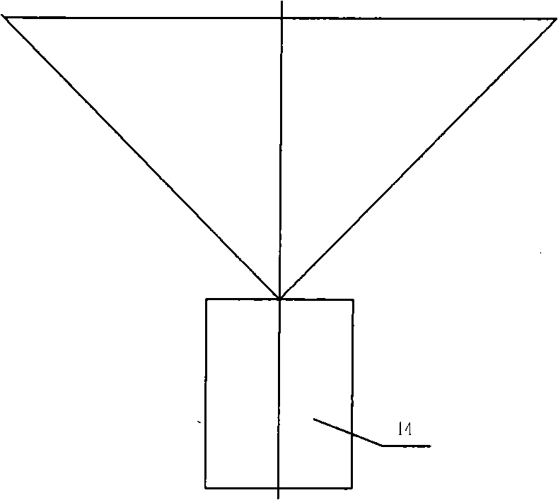
[0031] The monochromatic laser beam emitted by the semiconductor laser is transmitted through the optical fiber and then enters the optical lens system through the optical fiber connector. The focus of the beam is adjusted to a certain distance from the sealed glass cover. The laser beam passing through the convex lens is decomposed into a fan-shaped beam by the prism. The spatial distribution of the light source converted by the above optical system is an inverted trapezoidal fan-shaped light source.

[0032] The regular distribution of light intensity of fan-shaped light source in space is that the len...


PUM


Abstract

The invention relates to a laser line light source system with uniform lighting. In order to ensue the traffic safety of railway freight cars, a freight car (passenger car, motor train unit and locomotive) operation fault dynamic image detection system is promoted in a railway system in a system-wide manner. The product comprises a focusable prism with a step and a lens barrel (1), a prism (2) and a convex lens (3) are arranged in the large-diameter positions in the focusable prism and the lens barrel, a prism sheath (4) is sheathed outside the prism, the prism sheath is connected with a retainer ring (5), the small-diameter positions in the focusable prism and the lens barrel are in sleeve connection with an adjusting nut (6) and a laser lamp body (7), an optical fiber joint (8) is connected on one side of the laser lamp body, the optical fiber joint is connected with a semiconductor laser (10) through an optical fiber (9), and sealing glass covers (11) are connected at one end of the focusable prism and one end of the lens barrel. The laser line light source system can be applied in the detection of shooting operation fault dynamic images of freight cars, passenger cars, motor train units and locomotives.

Description

Technical field: [0001] The invention relates to a train operation fault image detection system captured by a line array scanning camera, in particular to a uniformly illuminated laser line light source system. Background technique: [0002] In order to ensure the safety of railway freight cars (passenger cars, EMUs, locomotives), the railway system has promoted the application of dynamic image detection systems for freight car (passenger cars, EMUs, locomotives) operation faults. In order to improve the performance of the dynamic image detection system for trucks (passenger cars, EMUs, and locomotives), a high-speed industrial line scan camera is used in the system to take pictures of the parts of the truck that need to be detected, and then the train inspectors scan the body of the truck by browsing the computer Part pictures for fault detection. [0003] The compensating light sources used in the existing system are traditional light sources with diffuse or reflective li...

Claims


Application Information

Patent Timeline
Patent Type & Authority Applications(China)
IPC IPC(8): F21S8/00F21V13/00F21V17/12H01S5/00
Inventor 何平马广江朱金良
Owner HARBIN KEJIA GENERAL MECHANICAL & ELECTRICAL CO LTD
Why Eureka
Try Eureka