Discharge lamp lighting device, power supply device and illuminator

A kind of lighting device, technology of discharge lamp

Inactive Publication Date: 2010-10-27
PANASONIC CORP
View PDF12 Cites 13 Cited by
  • Summary
  • Abstract
  • Description
  • Claims
  • Application Information

AI Technical Summary

Problems solved by technology

[0014]However, since the power conversion unit is installed in the subsequent stage of the DC power supply unit, when the abnormality determination unit on the power supply side determines that it is in an abnormal state, the abnormality determination unit on the load side It is often misjudged as an abnormal state in the middle
In addition, if it is configured to stop the operation of the DC power supply unit and the power conversion unit when it is judged to be in an abnormal state by the load-side abnormality judgment unit, the operation of the power conversion unit may not be substantially performed due to the above-mentioned erroneous judgment. The operation that the output power decreases

Method used


Image

  • Discharge lamp lighting device, power supply device and illuminator
  • Discharge lamp lighting device, power supply device and illuminator
  • Discharge lamp lighting device, power supply device and illuminator

Examples


Embodiment approach 1

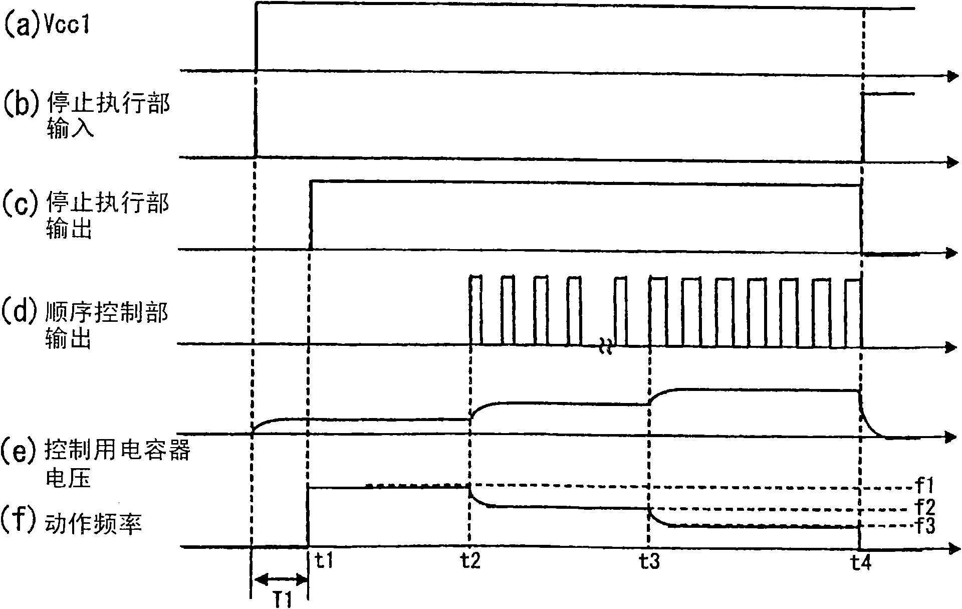
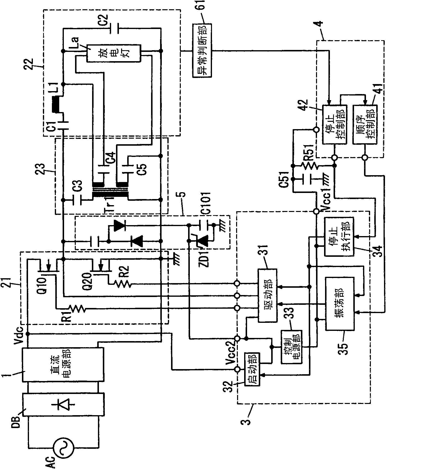
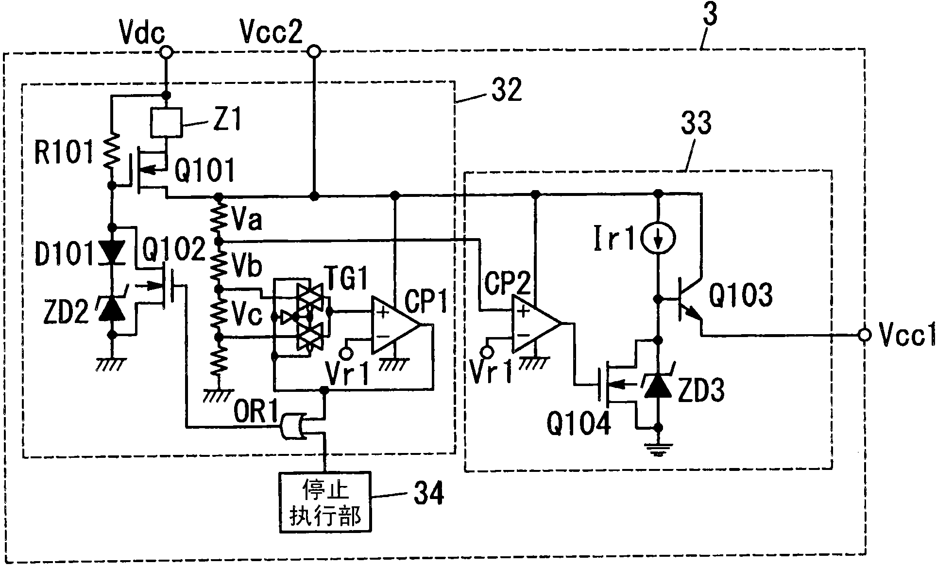
[0098] This embodiment is as figure 2 As shown, it is a device for lighting a general hot cathode type discharge lamp La having a pair of filaments (not shown in the figure), and includes: a rectification part DB composed of a known diode bridge, which is input from an external alternating current power source AC AC power full-wave rectification; DC power supply part 1, at least smoothing the output of rectification part DB to output DC power; switch part 21, equipped with two switching elements Q10, Q20 connected in series between the output terminals of DC power supply part 1 The circuit uses both ends of the switching element Q20 on the low voltage side (low side) as output terminals, and the resonant unit 22 is connected between the output terminals of the switching unit 21 to form a resonant circuit together with the discharge lamp La. That is, the switching unit 21 and the resonance unit 22 constitute a so-called half-bridge inverter circuit as a whole. In addition, th...

Embodiment approach 2

[0122] The basic configuration of this embodiment is common to that of Embodiment 1, and therefore the same reference numerals are assigned to the common parts and descriptions thereof are omitted.

[0123] This embodiment is as Figure 7 As shown, a sensor 62 for detecting a human body, and a human body determination unit 43a for determining the presence or absence of a human body within a predetermined detection range based on the output of the sensor 62 are provided. That is, the sensor 62 and the human body determination unit 43a constitute a so-called human body sensing sensor. The human body determination unit 43a is provided in the control integrated circuit 4, and both the sensor 62 and the human body determination unit 43a use the control voltage Vcc1 as a power source. As the sensor 62, for example, a pyroelectric sensor that detects heat rays (infrared light) radiated from the human body can be used. Since both the sensor 62 and the human body determination unit 43...

Embodiment approach 3

[0127] The basic configuration of this embodiment is common to that of Embodiment 1, and therefore the same reference numerals are assigned to the common parts and descriptions thereof are omitted.

[0128] This embodiment is as Figure 8 As shown, a well-known brightness sensor 63 is provided to detect the brightness of the space illuminated by the discharge lamp La. In the integrated circuit 4 for control, at least in the stable operation of the sequence control part 41, a signal generated with the brightness sensor 63 is provided. The regulation control part 44 which outputs the corresponding output. Such as Figure 9 As shown, the adjustment control unit 44 is connected to the control capacitor C103 via a resistor, and controls the operating frequency by changing the voltage across the control capacitor C103 similarly to the sequence control unit 41 . In this embodiment, the adjustment control unit 44 outputs a PWM signal similarly to the sequence control unit 41, but th...


PUM


Abstract

The invention provides a discharge lamp lighting device, a power supply device and an illuminator, which can prevent an overlarge electric stress on a circuit element or the discharge clamp after lighting the lamp. The device is provided with a direct current power supply part, a resonance part formed a resonance circuit together with the discharge lamp. A switch part for switching the DC power supply part and the resonance part, and a driving part for driving the switch part to output an alternated current to the discharge lamp from the resonance part through the voltage frequencies on two ends of a controlling capacitor. After the driving part is started and still cannot work in a preset stopping time T1, the driving part starts to work after stopping for the stopping time T1. The voltages on two ends of the capacitor can be stabled in the stopping time T1, so the overlarge electric stress on the circuit element or the discharge clamp can be avoided after starting, even if starting again after stopping for a short period of time.

Description

technical field [0001] The present invention relates to a lighting device for a discharge lamp, a power supply device and a lighting appliance. Background technique [0002] Conventionally, there has been provided a discharge lamp lighting device that includes a DC power supply unit that outputs DC power, a resonant unit that constitutes a resonant circuit together with the discharge lamp, and includes at least one switching element that is switched as the switching element is turned on and off. A switch unit for connecting the DC power supply unit and the resonator unit, and a drive unit for supplying AC power from the resonator unit to the discharge lamp by driving switching elements of the switch unit on and off (for example, refer to Patent Document 1 and Patent Document 2). The output power to the discharge lamp can be controlled by the relationship between the resonant frequency of the resonant circuit composed of the discharge lamp and the resonant unit, and the frequ...

Claims


Application Information

Patent Timeline
Patent Type & Authority Applications(China)
IPC IPC(8): H05B41/285H02H9/04H02M3/156
CPCY02B20/00
Inventor 滨本胜信大西尚树浅野宽之滨名哲也山中正弘
Owner PANASONIC CORP
Why Eureka
Try Eureka