

Flameless thermal oxidation apparatus and methods
A technology of thermal oxidation and oxidation chamber, applied in the field of thermal oxidizer to decompose organic compounds, thermal oxidizer to decompose organic compounds
- Summary
- Abstract
- Description
- Claims
- Application Information
AI Technical Summary
Problems solved by technology
Method used
Image

Examples
example 1
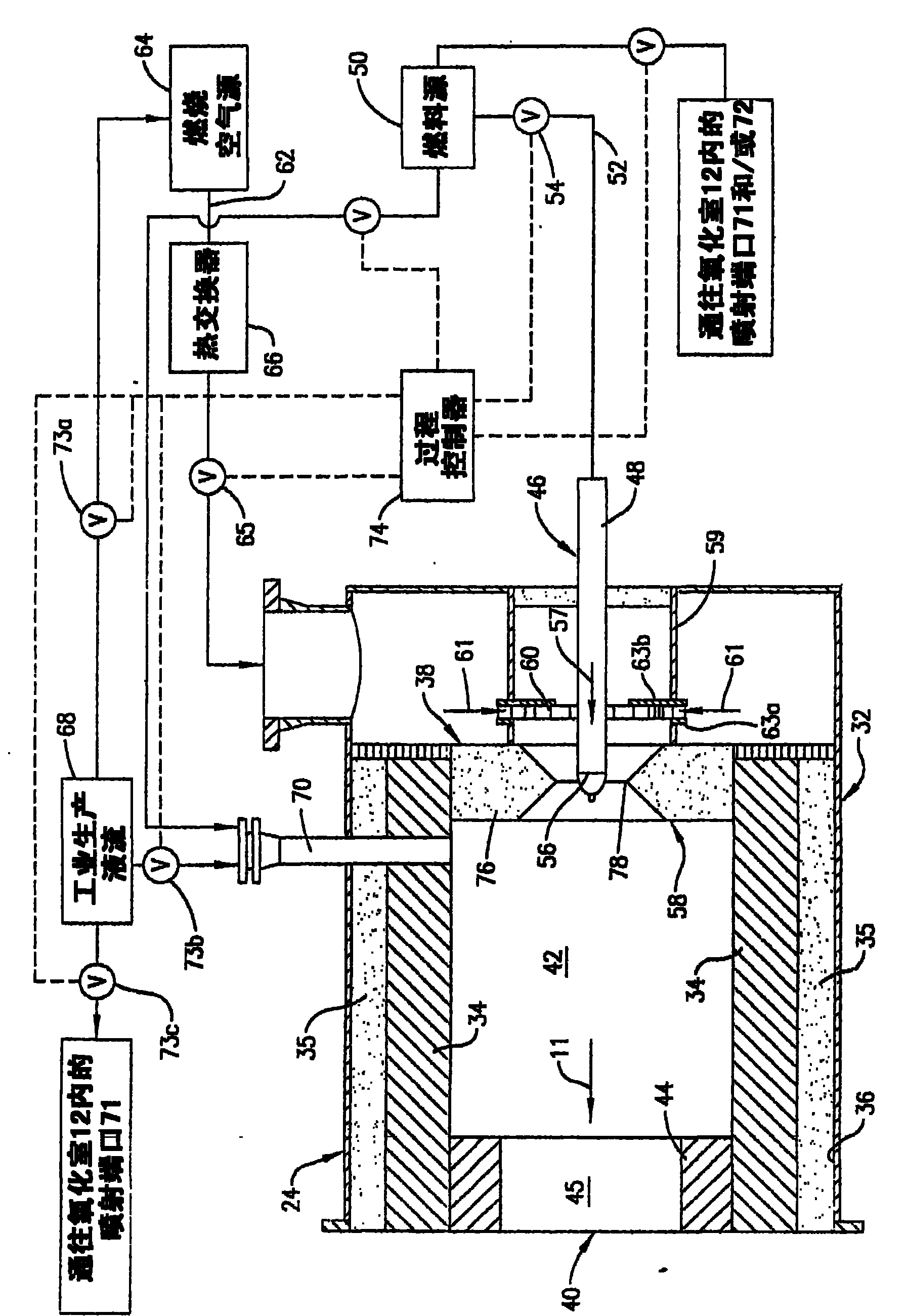
[0042] Combustion air in the form of air at room temperature is delivered into the antechamber 42 by the swirl vanes 60 at a flow rate of 114,000 scf / hr. Fuel in the form of natural gas at room temperature is injected into the antechamber 42 through the fuel tip 56 at a flow rate of 5,550 scf / hr. The fuel and combustion air mixture is ignited and burned with a visible flame until the oxidation chamber 12 reaches a temperature of 1,880°F. Once the oxidation chamber 12 is thus preheated, the fuel and combustion air are mixed more completely before passing the mixture through the burner throat 78 by pulling the fuel tip 56 back about 3.5 inches from the centerline of the burner throat 78 to extinguish the burner flame. The fuel and combustion air flow rates remain nearly constant, and the premixed flow of fuel and combustion air passes through the burner throat 78 into the antechamber 42 without a visible flame, and the combustion associated with the combustion of the fuel in th...
example 2
[0044] The test of Example 1 was repeated varying the following parameters: (1) the combustion air flow rate was reduced to 100,200 scf / hr, and (2) the fuel flow rate through the antechamber 42 was reduced by staging the fuel. The total fuel flow rate is 5,500 scf / hr and is split into 85.6% of the fuel that is premixed with all of the combustion air flow prior to injection into the antechamber 42 and the remaining 14.4% of the fuel passing through the The two flue gas ends 72 of the oxidation chamber 12 are sprayed. Fuel injected into the oxidation chamber 12 through the flue gas tip burns with a visible flame and is arranged to directly heat the refractory lining 16 to stabilize the flameless oxidation process within the oxidation chamber 12 . Due to this increased heat input, the outlet temperature of the oxidation chamber 12 is 1,990°F. As part of the fuel is combusted with a visible flame, the NOx content increases and varies from 6 to 12 ppm dry. The CO content was kept...
example 3
[0047] The test conditions presented in Example 3 demonstrate that after sufficient preheating of the refractory material 16 , the turbulent flame velocity is exceeded to allow flameless operation above the lower flammability limit of the air / fuel mixture within the antechamber 42 . The combustion air flow rate was 245,640 scf / hr, the natural gas flow rate was 18,357 scf / hr, and the thermal oxidizer operating temperature was 2,381°F. Combustion air and natural gas are premixed in the antechamber 42 to achieve a premixed fuel composition of 5.87 vol%, which is above the ambient temperature lower flammability limit (5 vol%). The oxidation process did not temper to the anterior chamber 42 , indicating that the turbulent flame velocity through the reduced diameter passage 45 was exceeded. NOx emissions for this process condition were 1.3 ppm dry and CO emissions were undetectable (<1 ppm dry).
PUM
 Abstract
Description
Claims
Application Information