
Permanent magnet canned pump

A canning and pumping technology, applied to pumps, pump devices, non-variable pumps, etc., can solve the problems of inability to maintain the tight bonding of ceramic materials, increase the centrifugal force burden of the fixed shaft, and insufficient corrosion resistance

Active Publication Date: 2011-12-28
ASSOMA
View PDF2 Cites 1 Cited by
  • Summary
  • Abstract
  • Description
  • Claims
  • Application Information

AI Technical Summary

Problems solved by technology

[0021] (1) The problem of insufficient bonding strength of plastic and ceramic materials due to the difference in thermophysical properties
[0022] (2) The strength reduction of plastic materials at high temperatures
[0023] (3) The problem that the centrifugal force increases when the operating speed exceeds the rated speed
[0025] (1) The strength of plastic materials: the strength of many corrosion-resistant materials cannot be compared with that of ceramic materials, especially when the temperature increases, the material strength decreases greatly, and some plastics still have good strength when the temperature increases, but their corrosion resistance is insufficient.
[0026] (2) Thermal deformation of plastic materials: Many corrosion-resistant plastic materials have poor thermal deformation resistance and cannot maintain close bonding with ceramic materials
[0027] (3) High-speed centrifugal force problem: the mass of the motor rotor is large, and there is a gap required for lubrication between the hydrodynamic pressure bearing and the fixed shaft, which will increase the burden on the centrifugal force of the fixed shaft, and the centrifugal force will increase as the second power of the speed ratio , when the pump is running at a higher than rated speed, the fixed shaft must bear higher centrifugal force
[0029] British Patent No. GB2417981 adopts the design of cantilever fixed shaft structure, and uses high rigidity structural parts at the bottom of the sealed back cover to shoot together with the fixed shaft, so that the plastic material and the fixed shaft can be tightly combined and the supporting force of the shaft can be improved. This patent uses The material is high-temperature-resistant and high-strength engineering plastics, but this material cannot meet the needs of highly corrosive liquids such as hydrofluoric acid; since the previous patent is used for engine cooling water circulation, there is no corrosion resistance problem, but As far as the plastic material is used in corrosion-resistant applications, the combination of the fixed shaft and plastic, and the combination of other metal parts and plastics, cannot completely seal highly corrosive liquids; secondly, the cylindrical part of the back cover The thickness is thin and the rigidity is insufficient, and it is easy to cause displacement or misalignment of the fixed shaft
[0030] In addition, Japanese Patent No. JP2005299559 is a fixed shaft structure with bilateral support. A tripod is used at the pump inlet and an additional rigid structural member is used at the bottom of the rear cover to strengthen the support of the fixed shaft; the focus of this patent is on the The weight of the rotor is designed to reduce weight. This feature effectively solves the weight problem of the rotor; but its structure still cannot meet the problem of softening and deformation of the plastic material on the cylindrical part of the back cover under high temperature, the deformation of the tripod at high temperature, and the second rigidity. Structural parts must be used in highly corrosive liquids. This patent is only applicable to the use of non-corrosive liquids in engine cooling water circulation
[0031] The above solutions cannot provide a complete answer to the high-corrosion and high-temperature chemical liquid process, so the present invention will provide the best solution to the above problems to meet the needs of users

Method used


Image

  • Permanent magnet canned pump
  • Permanent magnet canned pump
  • Permanent magnet canned pump

Examples


Embodiment Construction

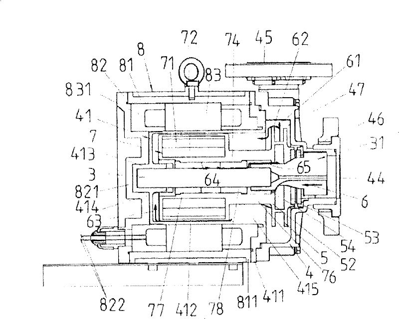
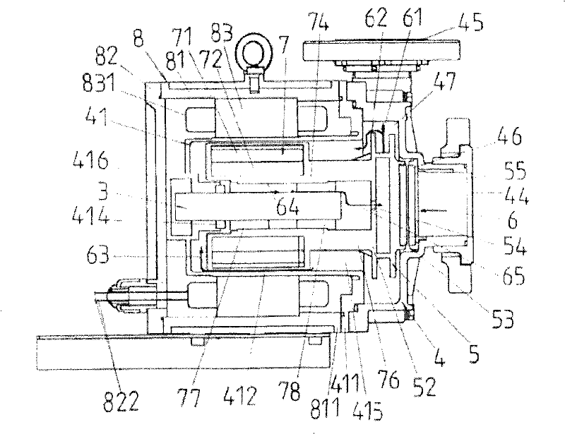
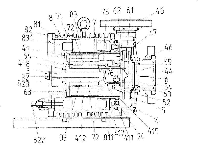
[0101] see image 3 As shown, the permanent magnet canned pump of the present invention is a cantilever fixed shaft structure; the pump is composed of a pump front cover 4, an impeller 5 and a canned motor 8, wherein:

[0102] The pump front cover 4 is provided with an inlet 44, an outlet 45 and a channel space 47 for accommodating the impeller 5; The push rings 53 are coupled together to form an axial thrust bearing;

[0103] The impeller 5 is installed inside the pump front cover 4, and the impeller hub plate 55 is provided with a plurality of openings 54 to be used as return holes for internal lubrication circulation, and also as balance holes for eliminating axial thrust; the impeller hub 52 is an axial The extended ring structure is used to combine with the axial extension 76 of the motor rotor 7, so that the impeller 5 and the motor rotor 7 are integrated;

[0104] The canned motor 8 is composed of a motor stator 83, a motor middle frame 81, a motor rear frame 82, a pu...


PUM


Abstract

The invention provides a permanent magnet canned pump, especially a plastic or plastic-lined pump suitable for the transportation, pressurization and circulation of highly corrosive chemical liquids. The support structure of the rotor system is improved to provide A high-rigidity cantilever-type fixed shaft structure to meet various needs. The characteristics of the high-rigidity cantilever-type fixed shaft structure include: a high-rigidity metal shaft, which is fixed on the rear frame of the motor and forms a fixed shaft with a ceramic bushing, a A ceramic shaft sleeve is used to combine with the metal shaft to form a fixed shaft to support the rotation of the motor rotor and axial thrust function. A motor rear frame is used to fix the metal shaft to strengthen the support strength of the fixed shaft, and cooperate with the sealed rear cover To provide the function of sealing the motor coils, a sealing back cover has a central opening for the metal shaft to pass through, and its inner space is used to accommodate the motor rotor and provide the function of sealing the motor stator coils.

Description

technical field [0001] Because the producers pursue the maximum efficiency of production equipment, they hope that the same pump can be used in high flow and low head, and can also be used in high head and low flow conditions. However, the production line managers do not consider many factors. There must be many pumps of different specifications in standby at any time, so that the permanent magnet canned pump is gradually valued by users; the present invention also makes further improvements to the above solutions, and the innovative pump structure enables the permanent magnet canned pump to meet needs for various uses. [0002] The present invention provides a canned shaft-sealless pump driven by a permanent magnet motor, hereinafter referred to as a permanent magnet canned pump, which is especially suitable for plastic or plastic internal pumps for the delivery, pressurization and circulation of highly corrosive chemical liquids. Lined pump; because the highly corrosive che...

Claims


Application Information

Patent Timeline
Patent Type & Authority Patents(China)
IPC IPC(8): F04D13/04
Inventor 简焕然王锦城施志宽
Owner ASSOMA
Learn More