Light source module of LED street lamp

A technology of LED street lamps and light source modules, applied in the field of LED lighting, can solve the problems of reducing the overall luminous efficiency of LED street lamps and increasing losses, and achieve the effects of enhancing energy conservation, emission reduction, and improving luminous efficiency.

Inactive Publication Date: 2010-11-10
厦门市信达光电科技有限公司
View PDF0 Cites 12 Cited by
  • Summary
  • Abstract
  • Description
  • Claims
  • Application Information

AI Technical Summary

Problems solved by technology

The disadvantage of this conventional LED street lamp structure is that the secondary optical lens must be used to meet the light distribution requirements. Since there is a gap between the secondary optical lens 3" and the LED device 1", there are different medium interfaces, which increases the light from the The loss during the propagation process of the LED chip to the target irradiation area leads to a decrease in the overall light efficiency of the LED street light source.

Method used


Image

  • Light source module of LED street lamp
  • Light source module of LED street lamp
  • Light source module of LED street lamp

Examples


Embodiment 1

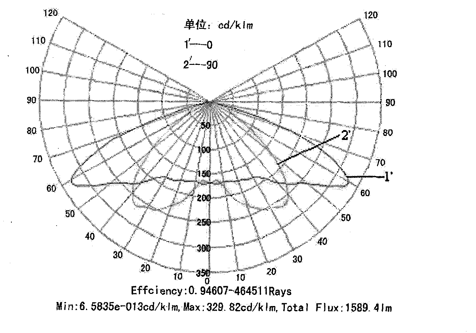
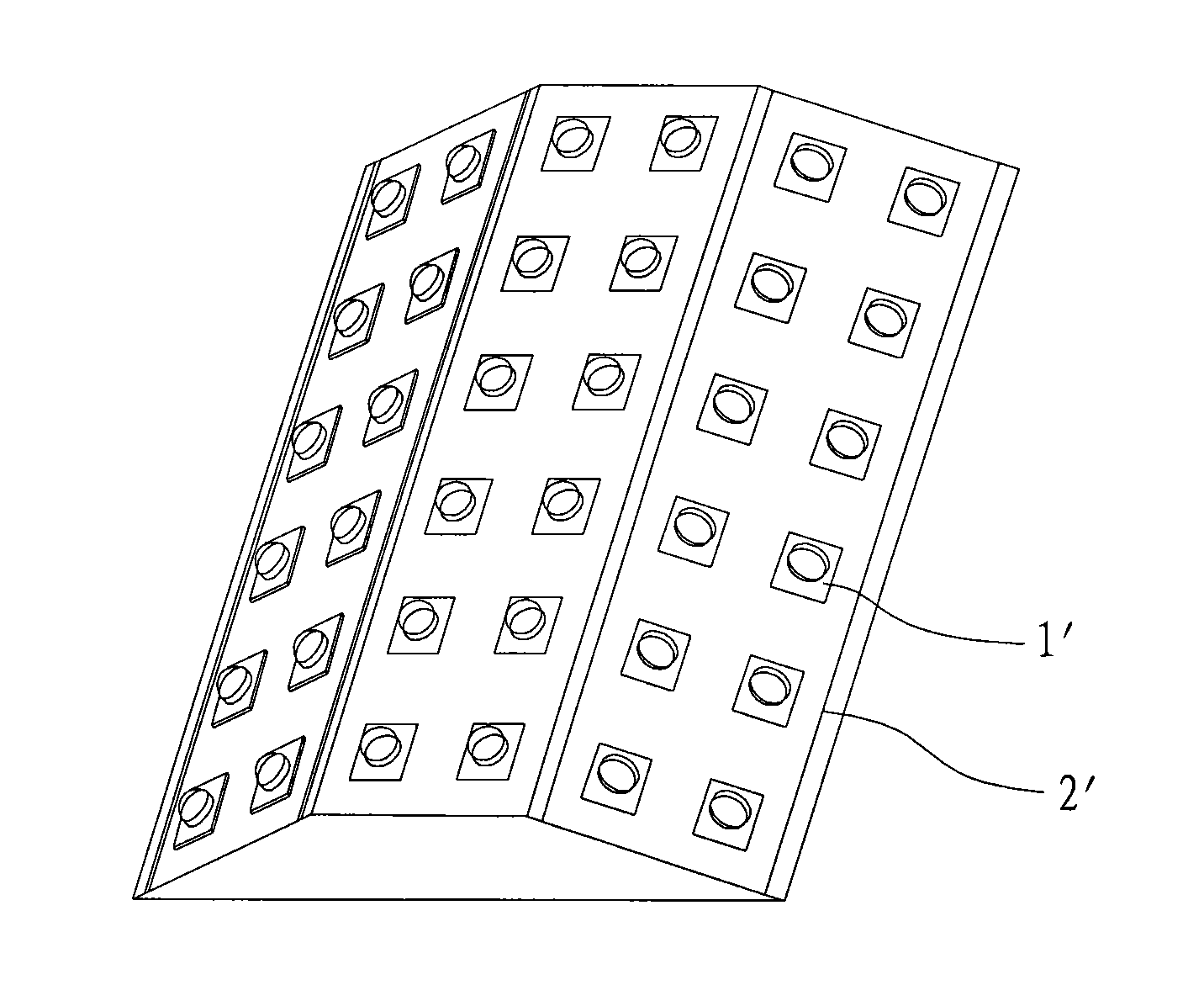
[0042] Adopt 0.98×0.98mm 2 The high-power LED chip is used as the illuminant of the street light source module, which is packaged in a single chip, and silica gel with a refractive index of 1.41 is selected as the packaging material. The LED street lights will be used for 4-lane road lighting. The width of the road is about 15m, and the width of the isolation belt and the emergency parking belt is initially set at 20m. There should be a small amount of superposition between the beams of street lamps to avoid forming an overly dark irradiation area, which requires the irradiation angle of LED street lamps to reach 115-125° along the road. In order to achieve the above-mentioned goals, the one-time encapsulation and molding LED light source module (such as figure 2 and image 3 As shown) consists of a PCB board 11 with a reflective cup, an LED chip 12 coated with phosphor powder, and a transparent package body 13 . The size of the PCB board 11 is 40×40 mm. There are 16 refle...

Embodiment 2

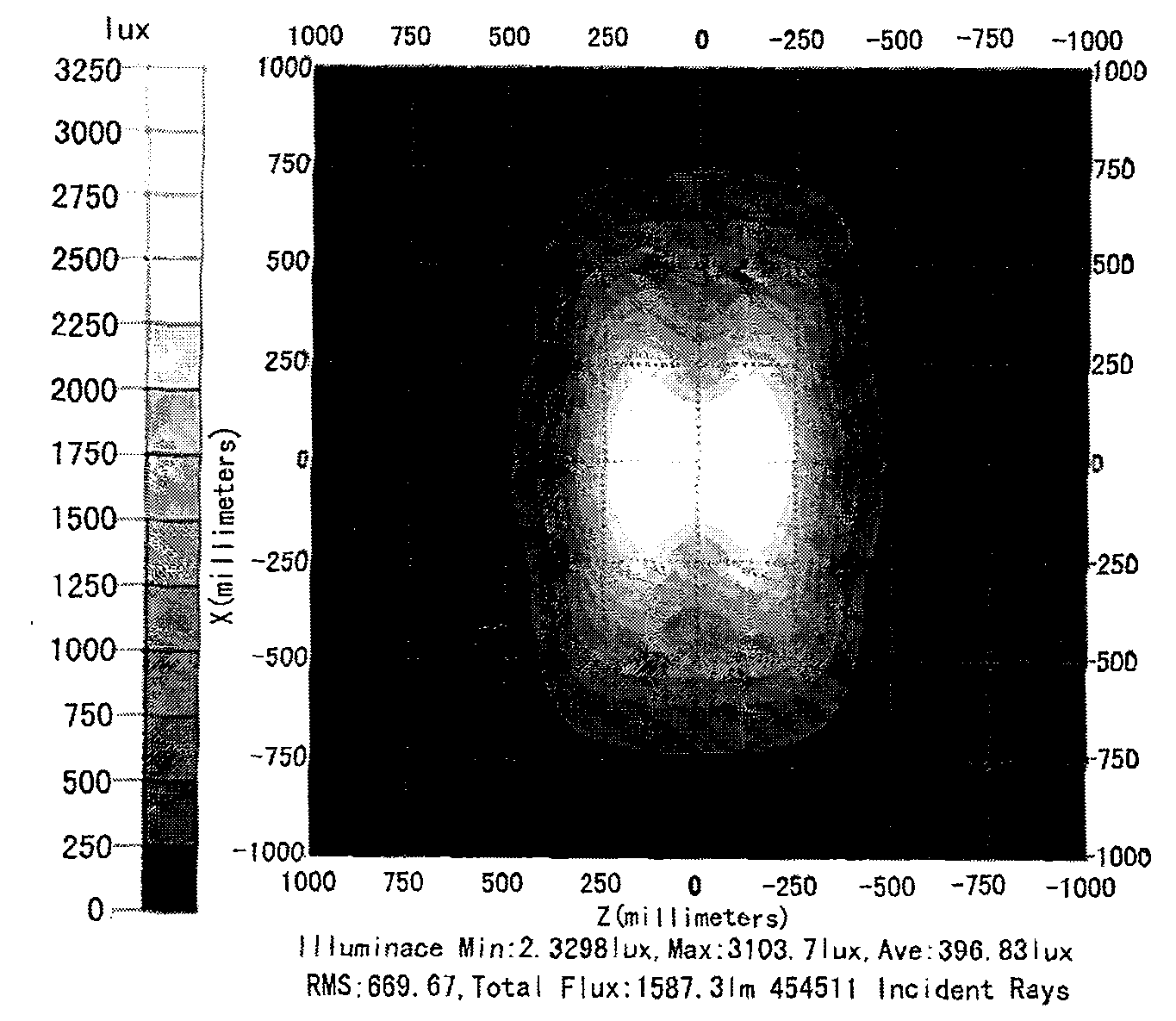
[0044] Eight LED light source modules described in Embodiment 1 are assembled into LED street lamps. The arrangement of the LED light source modules is 4×2, and its structure is as follows: Figure 5 shown. The LED street light has a total of 128 light-emitting units, its power consumption is about 140W, and its total luminous flux is about 13,340lm. When the irradiation distance is 10m, the polar coordinate light intensity distribution and illuminance distribution of the LED street lamp are obtained as follows: Figure 8A and 8B shown. It is not difficult to see that the illumination angle and light intensity distribution of the LED street lamp in the direction along the road and perpendicular to the road are consistent with the LED light source module; The number of light-emitting units and the distance of the illuminance test are different.

[0045] Embodiment 1 and Embodiment 2 show that, using the LED street light source module of the present invention, when the LED l...


PUM


Abstract

The invention discloses a light source module of an LED street lamp, comprising a plurality of LED devices and an LED light source support body, wherein the LED devices are stuck to the light source support body; the LED devices mainly comprise PCBs, LED chips coated with fluorescent powder and transparent packaging bodies; the LED chips are arranged in the centers of the reflection cups of the PCBs; the transparent packaging bodies cover the LED chips; the lower parts of the transparent packaging bodies are filled with the reflection cups and are in contact with the LED chips; and the upper parts of the transparent packaging bodies are exposed outside the reflection cups. Since the transparent packaging bodies of the invention cover the LED chips, and the lower parts of the transparent packaging bodies are filled with the reflection cups and are in contact with the LED chips, the loss of light in the process of propagating from the LED chips to a target radiation area because different medium interfaces exist between a secondary optical lens and the LED devices when the secondary optical lens is adopted to carry out light distribution is avoided , and the integral luminous efficiency of the LED street lamp is improved.

Description

technical field [0001] The invention relates to the technical field of LED lighting, in particular to an LED street light source module. Background technique [0002] With the continuous improvement of LED luminous efficiency and reliability and the continuous reduction of production costs, the use of LEDs for road lighting has become a technical development trend in the lighting field. Although the photopic luminous efficacy of white LEDs is still lower than that of high-pressure sodium lamps, due to the wide spectrum of white LEDs, it is expected to obtain higher luminous efficiency than high-pressure sodium lamps in mesopic state by adjusting their spectral energy distribution reasonably. Moreover, due to the good orientation of the LED light source and the high utilization rate of light energy, the use of low-power LED street lights can replace high-power high-pressure sodium lamps, which has very prominent advantages in energy saving and emission reduction. In addition...

Claims


Application Information

Patent Timeline
Patent Type & Authority Applications(China)
IPC IPC(8): F21S8/00F21V7/00F21V9/10F21V19/00F21V15/02H01L33/00F21Y101/02F21W131/103F21V9/40
CPCY02B20/72
Inventor 郑代顺黄智炜孙会忠
Owner 厦门市信达光电科技有限公司
Why Eureka
Try Eureka