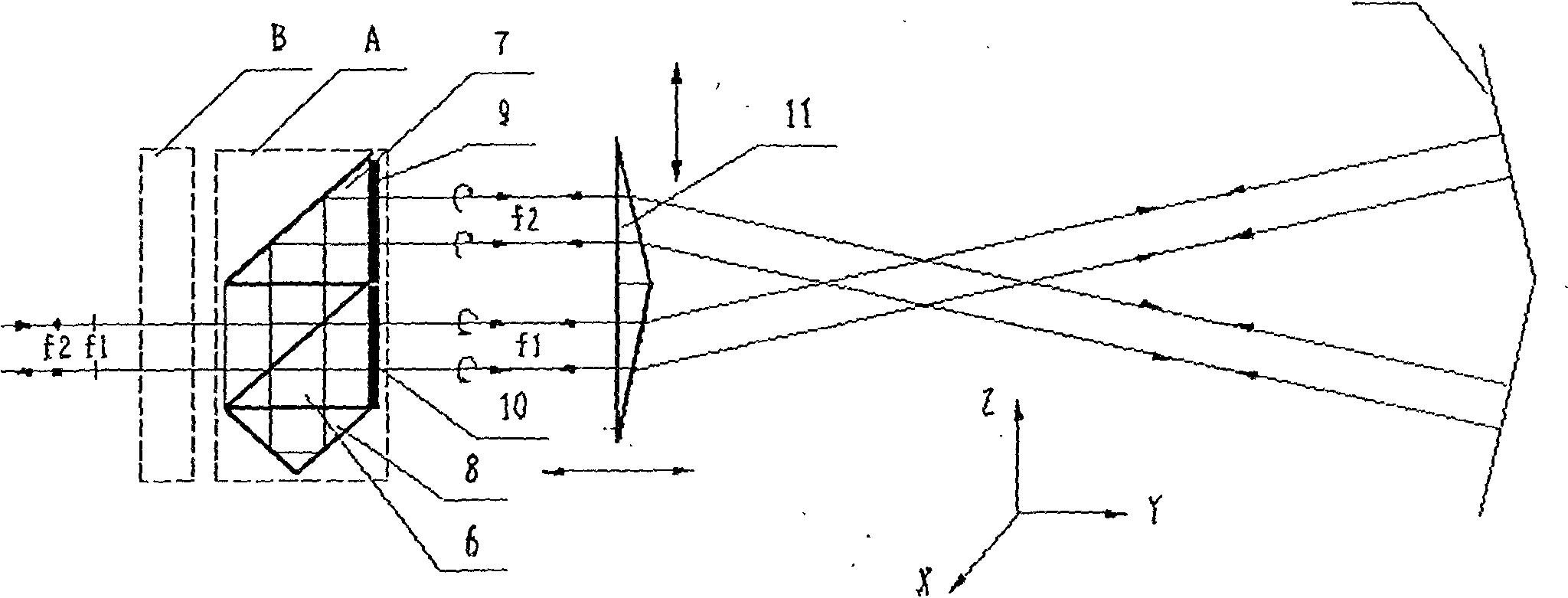
Laser straightness interferometer light path system
A straightness and interferometer technology, applied to instruments, optical devices, measuring devices, etc., to achieve the effects of reduced length, increased measurement sensitivity, and simple structure
Inactive Publication Date: 2010-11-10
CHENGDU TOOL RES INST
View PDF4 Cites 4 Cited by
- Summary
- Abstract
- Description
- Claims
- Application Information
AI Technical Summary
Problems solved by technology
[0004] The refractor 2 is composed of a light analysis mirror (coated with a semi-transparent and semi-reflective film) and a total reflection mirror. Since the light will lose 50% of its energy when passing through the light analysis mirror, the laser output from the laser head 1 needs to go through light analysis twice. Mirror 2 returns, if other energy losses are not considered, the returned light carrying measurement information is only 25% of the energy of the outgoing light. Due to the large gain of the dual-frequency laser interferometer system, such losses can be ignored, but in single-frequency laser interferometer In the instrument system, this shortcoming is fatal
Method used
View moreImage
Smart ImageViewing Examples
Examples
example 1
[0033] Example 1: Double optical wedge material: K9 glass
[0034] Refractive index: n=1.51630
[0035] Optical wedge angle: α=2.64°
[0036] Calculate according to formula 2: S=0.191
example 2
[0037] Example 2: Double optical wedge material: ZF7 glass
[0038] Refractive index: n=1.80600
[0039] Optical wedge angle: α=4°
[0040] Calculate according to formula 2: S=0.504.
Login to View More PUM
 Abstract
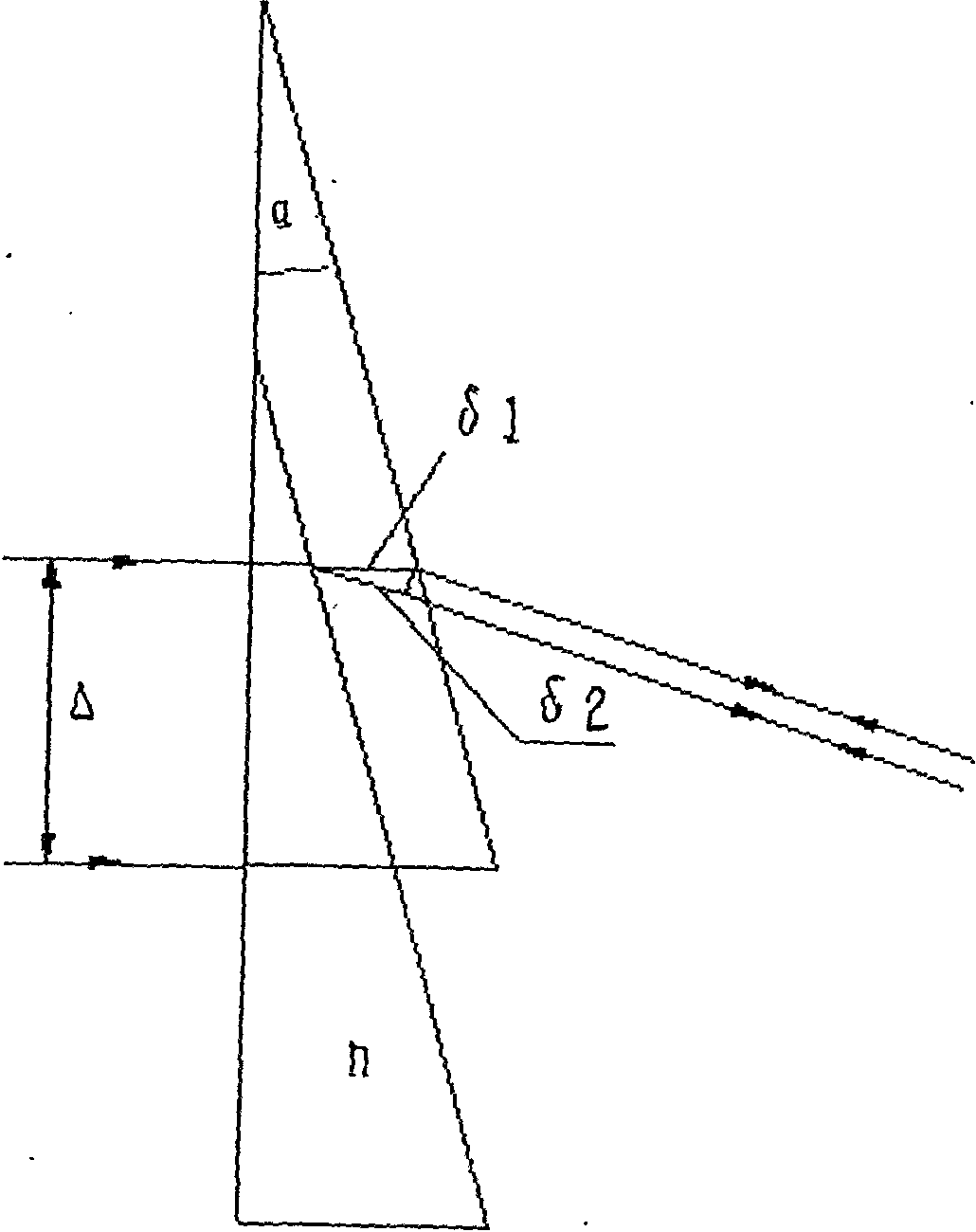
The invention relates to a laser straightness interferometer light path system which solves the problem of low measuring sensitivity of the traditional straightness interferometer. The laser straightness interferometer light path system comprises a laser head (1), an assembly (A), a double optical wedge (11) and a biplane reflecting mirror (12). The assembly (A) is formed by binding a polarizing beam splitter (6), a reflecting mirror (7), a pyramid prism (8) and quarter wave plates (9) and (10) into an integer. The double optical wedge (11) is formed by binding an upper wedge and a lower wedge, and the bottom surface of the upper wedge is opposite to that of the lower wedge. f1 light and f2 light emitted by the laser head (1) respectively pass through the upper wedge and the lower wedge of the double optical wedge (11) after beam splitting by the assembly (A), vertically irradiate the two reflecting planes of the biplane reflecting mirror (12), and go back the same way. A measured object and the double optical wedge (11) move along the Y direction; when a displacement is generated in the Z direction, i.e. a straightness error exits, the f1 light and the f2 light produce opposite optical path differences, and thus, the straightness error value can be calculated out. The invention has high measuring sensitivity, compact structure, low cost and convenient assembly.
Description
Technical field: [0001] The invention relates to an optical path system of a laser straightness interferometer, which is related to the straightness measurement of guide rail pairs of precision equipment. Background technique: [0002] The laser straightness interferometer uses the method of differential interference to measure the straightness error. Due to its high precision and large measuring range, it is widely used in the straightness detection of guide rails in precision equipment such as machine tools and coordinate measuring machines. [0003] The optical path system of the laser straightness interferometer is composed of a laser head and a straightness interferometer. figure 1 It is a straightness measurement accessory of Agilent Company. The linearly polarized light f1 and f2 with polarization directions perpendicular to each other emitted by the laser head 1 are split at a certain angle by the wllaston prism 3 and directed to the double mirror 4 . The laser head...
Claims
Login to View More Application Information
Patent Timeline
 Patent Type & Authority Applications(China)
IPC IPC(8): G01B11/26G01B9/02
Inventor 梁军邓上舒阳黄宁秋羡一民
Owner CHENGDU TOOL RES INST
Features
- R&D
- Intellectual Property
- Life Sciences
- Materials
- Tech Scout
- Unparalleled Data Quality
- Higher Quality Content
- 60% Fewer Hallucinations
Learn More Browse by: Latest US Patents, China's latest patents, Technical Efficacy Thesaurus, Application Domain, Technology Topic, Popular Technical Reports.
© 2025 PatSnap. All rights reserved.Legal|Privacy policy|Modern Slavery Act Transparency Statement|Sitemap|About US| Contact US: help@patsnap.com


